When you click on links to various merchants on this site and make a purchase, this can result in this site earning a commission. Affiliate programs and affiliations include, but are not limited to, the eBay Partner Network.
WOW! Thanks for posting those photos!
We can really get somewhere now!!!
Some very important things will come up here! One will be comparing measurements!
Originally Posted by Trucknewowner
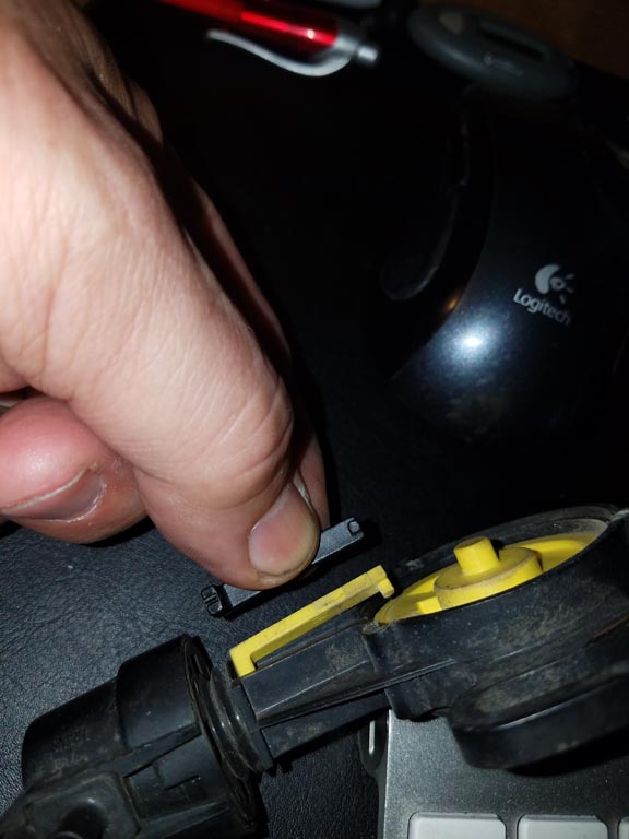
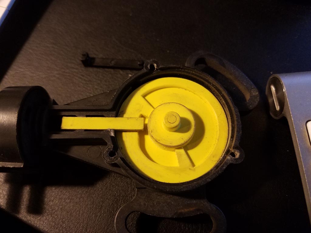
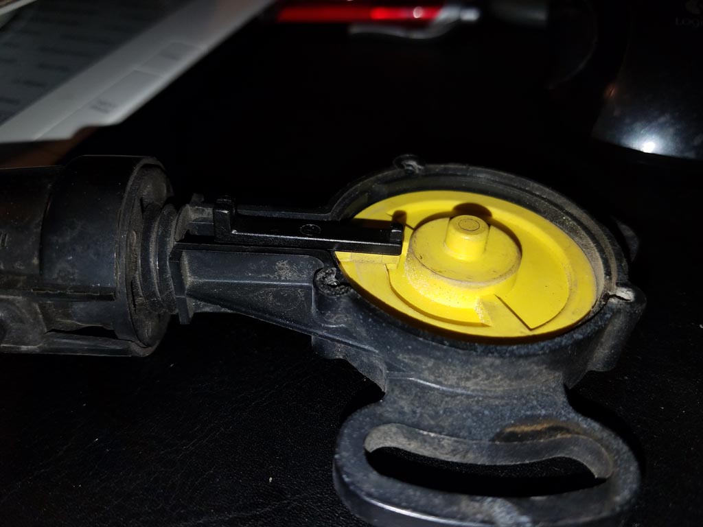
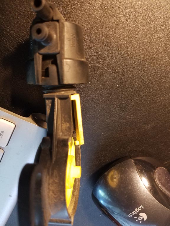
Finally the GM VRV apart:
The color of the rod is black, and the vacuum assembly is a black part with two vacuum fittings. If I'm understanding the whole part swapping idea, I should be able to lift the black rod that rides in the yellow cam and place it to the side, then turn (unscrew) the black plastic part with the vacuum fittings, and the entire thing will tread off without further disassembly (or breaking the glued in tabs).
NO!DO NOT TRY IT THAT WAY.DO NOT TRY TO TURN THE UPPER VALVE ASSEMBLY. You can damage or break the spring that the connecting rod is attached to and possibly damage internal parts of the valve!
You CAN'T disconnect the top of that rod from the spring until the castle type nut is unscrewed and THEN the Vacuum Valve Assembly, the Link Rod and Spring will be removed while all connected together. ONLY THEN can the rod that engages with the cam be disconnected from the spring BUT YOU MAY NOT HAVE TO DISCONNECT THAT ROD FROM THE SPRING!
WE MAY BE ABLE TO USE THE BLACK GM PLASTIC LINK (AND OF COURSE THE NEW VALVE ASSEMBLY- WHICH IS THE TOP PART) WITH THE FORD VRV CAM AND FRAME.
This is VERY EXCITING! So exciting that I wrote it in all CAPS because if that new GM plastic rod will work, (if the dimensions are right, the spring should also work and WE ARE ALL SET FOR A VIRTUALLY NEW FORD VRV!
Isn't that exciting!
Question: do I need the yellow cam? Or should I be able to use the yellow cam in the old Ford VRV?
NO, the GM VRV Cam is reversed.
If I can use the Ford cam, then I can just take the vacuum assembly and thread it onto the Ford VRV, place the black rod in the slot of the Ford cam and put the original cover back on, and it will be complete.
I HOPE YES! BUT:We definitely need to compare and confirm some dimensions first!
We may have to use the OLD FORD spring that connects from the LINK ROD to the internal diaphragm due to difference in spring lengths OR stretch the new GM spring to match the length of the old FORD spring. You are going to have to disassemble the New GM VRV as I described above and then disconnect the rod from the spring AND disconnect the spring from the diaphragm assembly which is SIMPLE but don't do this until you are prepared because there might be that same tiny part in there which I described earlier.
I want to hurry and finish this and post it befor you make a possible mistake in taking that GM assembly apart.
(I might be able to use the yellow cam from the GM VRV since it is just sitting in the well, and it looks similar to the Ford VRV.) That's it so far, I need to get a junk VRV for the next step.
Nope, you can't use the GM cam. It's completely reversed because it went on the opposite side of the injection pumps in the GM Trucks.
Just a quick note to save you some time, the black connecting rod can be lifted straight up, rotated around the connecting rod 180 degrees, and lifted gently 90 degrees and it is then disconnected from the metal link with the vacuum part. Here is a picture of the rod and the end of the thin connecting rod with a little bend on the end. I'd need to use needle nosed pliers to reassemble it. It looks like the castle nut could be spun off now that the rod is disconnected?
Just a quick note to save you some time, the black connecting rod can be lifted straight up, rotated around the connecting rod 180 degrees, and lifted gently 90 degrees and it is then disconnected from the metal link with the vacuum part. Here is a picture of the rod and the end of the thin connecting rod with a little bend on the end. I'd need to use needle nosed pliers to reassemble it. It looks like the castle nut could be spun off now that the rod is disconnected?
PLEASE don't remove the castle nut or the top or try to unscrew it.
We need to know some dimensions first, exactly as it came from the factory as you showed it in your picture with the plastic rod in it's proper place. That is the factory calibration so it would be very good to know exactly what certain dimensions are before anything gets changed. This is the best way to approach this job. It's probably OK that you removed the plastic link and we can still get the dimensions without reconnecting it.
Do not re-connect it until the top is off (it will be much easier) and I'm suggesting this to you for good reasons.
I knew you could take it off but it's much easer and SAFER to avoid damage to the parts to wait until the top is removed with the link still attached, probably moreso when reconnecting it. Otherwise you'll be putting undo stress on that metal part which in the FIORD VRV is a thin metal coil spring and what is seen in your photo is one end of the spring which is straight with the 90 deg. bend in the end. That spring can break easily. (see further below)
chaotic_robot mentioned that he had to adjust the valve assembly by turning that castle nut (down or up) after he had put everything together, so that's one reason why we need to know some location dimensions to determine the original factory calibration before taking it apart.
Everything looks like it is going to be an exact fit into the FORD VRV with the same existing calibration of the GM part!
We just need to confirm that which will also make your job easier, safer for the parts and more precise.
Sorry to repeat- too tired to edit: In the FORD VRV, that metal piece with the 90 deg. bend that connects to the plastic link is the straight end of a thin coil spring, the other end connected to the brass tube which holds the blue rubber diaphragm in the valve. If that spring happens to become disconnected from that brass tube (which is now much easier to accidentally happen with the black plastic link removed, you could lose a very tiny and essential piece that is inside of that brass tube. The spring attached to the tube is the only thing that keeps that very tiny part from falling out and being lost.
When I received the VRV that I have (in the photos) that spring had already been broken, precisely because someone had tried to unscrew or remove the top part without disengaging the Link from the cam.
All of these things are good reasons to be prepared and know how it all comes apart and is put back together without making any mistakes which is partly what I'm trying to help with in this topic.
The other part of my interest is in the precision and dimensioning of the design of these VRVs (Especially in a brand new state like yours) so duplicate parts can be made for repairs and rebuilds of the FORD VRV.
I won't burden you by asking for any extra time from you to make any precision measurements on of your GM VRV because I ordered the same GM part that you have and I can do that when I get it.
HOWEVER, a few measurements from you, which I can show you in photographs here using the FORD VRV and it's important dimensions and than comparing those with your GM VRV will, be very valuable to YOU and to everyone else who reads this thread and wants to do the same or similar repair.
My situation at the time I began writing this post is TRYING to find one square foot of clear space where I can take the photos. Also I need to find that broken spring which is loses on my desk buried somewhere here.
So I'll set up to do that right now OR I can post a photo or two which I had promised around April 23rd.
BY THE WAY. I confirmed that the wires gadget in the GM VRV is a throttle position sensor. I looked that up for a 1996 P30 Chev. truck with 6.5L diesel and a Standard shift transmission (not automatic) and the throttle position sensor mounts exactly where the GM VRV would be mounted for an automatic transmission. It even has the same mounting adjustment slots. So with the automatics they incorporated the throttle position sensor into the VRV - position of the VRV cam.
Secondly, chaoticrobot suggested that the same manufacturer may have built both the FORD and the GM VRV's. I am very much inclined to agree, because it is looking like most of the internal parts and even dimensions are identical. Probably from the same PATENT which I was not able to find (yet).
THIRDLY, there is ANOTHER ACDELCO, GM VRV with a different part number and WITHOUT the wires and throttle position sensor which was apparently used in model years before that throttle position sensor was introduced. It is probably essentially the same for the parts WE need. It's less expensive by around $20.
You can see both parts, the part numbers and which vehicles they fit here: ACDelco Parts EDIT: At that web page you have to enter the part numbers, which are:14057219 (without the wires) and 23500822 (with the wires)
The one without the wires is showing the back side of the cam which engages with the Injection Pump throttle shaft when it is installed. The back side of that cam is exactly the same as the cam in the FORD VRV.
The LAST model year shown for the ACDELCO GM VRV with the sensor is 1996. At some point in the future, these GM VRVs will probably be obsoleted and become unavailable just like FORD VRV. I can only guestimate that this might happen within the next 2 years, Maybe sooner maybe later.
I hope this can wait until some time tomorrow for me because I'm too tired to do what I had intended to do. The most important of which is to get some photos posted of a few important dimensions in the FORD VRV so we can compare and determine the best way to do this "fix." It is 3:17 AM and I really need to catch up on some sleep.
THANKS
Last edited by Fixnstuff; 05-07-2017 at 05:43 AM.
Reason: Add part numbers
With a part in hand the parts of this that fail or wear out could probably be 3d printed, for those of us with access to one. Unless it's the diaphragm that fails, not sure how one would source a replacement for that.
Thanks fixnstuff, for keeping me out of trouble, or trying to at least! I'd already had the connecting rod out, so removing it again for the picture seemed safe enough. I'll keep my fingers off it for now! I'll have my broken VRV soon, since I got the working VRV from cadunkle on eBay. I wish the forum hadn't short circuited the process of contacting cadunkle - not being able to PM him (since I had only been on the forum for 7 days instead of 10) was painful and expensive.
I'm going to have a mechanic install the working VRV, he says I need a scanner and a .45 hundredth inch shim to set it. (the dimension of hundredths for the .45 size is in question, since it was on the phone, but i'm certain about the .45 since he was moaning about Ford and saying they should have used a .5...).
After the fact I will carefully remove the old non-working VRV cover and see what's inside. It may be that just replacing the connecting rod will by sufficient, so I'll have a good backup, It looks like there are a number of parts in common as fixnstuff says! Even the yellow GM cam looks to by identical, except for the visible spring on the bottom where it mounts. But the Ford casing may be hiding the spring instead? More as it happens, and thanks fixnstuff for his meticulous work!
I was hoping it wasn't you that paid that price, couldn't believe how much it ended up selling for. If it weren't for the forum issue I would have sold it directly to you for a very fair price. I'm glad you've got the part you need though. I'll get it in the mail tomorrow. Here's to hoping for a solution to replacing this NLA part with new bits.
FINALLY, I have some time to post some images with a couple of measurements. I took the photos earlier today but they are still in the camera. A bit of photo processing and confirming dimensions and I'll be ready! Check and compare those dimensions on your new GM VRV, Trucknewowner, and you should be ready to use it!!
Originally Posted by Trucknewowner
Thanks fixnstuff, for keeping me out of trouble, or trying to at least! I'd already had the connecting rod out, so removing it again for the picture seemed safe enough. I'll keep my fingers off it for now!
NO PROBLEM, you didn't harm anything. I felt uncomfortable after telling you how to handle YOUR part but some people are very careful and good at disassembling/reassembling small parts while some people are not as careful. I just don't want anyone to make a mistake that damages any component.
I'll skip part of your post and comment on that later
I'm going to have a mechanic install the working VRV,
BEFORE you decide to install the 'working VRV' you need to remove the side cover, disengage the plastic link from the cam ramp and inspect it to see how much is left of the little post that slides on the cam ramp as the throttle is opened and closed = to see how much has been worn off of it and how much is left. That will determine how long it is going to last, the service life left in terms of miles/kilometres. It only gets worn when the the throttle is moved up from the lowest idle position (low idle) and down again - whenever the throttle position changes. Wear depends upon how the truck was driven. Related to mileage accumulation: less wear at constant speeds, more wear with stop and go city driving or with frequent changes in throttle positions.
I do not know how many miles/kilometres the original VRVs were good for. Some well seasoned guys who bought new trucks with the C-6 might remember from their experience. It would vary of course but if it lasted 80-100k miles I would say that's pretty reasonable for a truck that's been driven at an average use, maybe more if driven lots of highway miles and less for mostly stop and go driving. That is only a guess-ti-mate based on what I would accept as a reasonable replacement mileage for a part like that but I am hoping it is more.
You will have to make a decision with the various parts/components that you have and exactly what you want to install in your truck based upon what you find in your inspections. ALSO, you need to inspect your existing VRV that is in the truck now in the same way.
I would REALLY like to see photos of bothof your FORD VRV plastic links, the sides with the post that slides on the cam ramp. Those would help me a bunch as a reference. ALSO a photo of the same side of the plastic link you just removed from the GM VRV. I've actually not seen this post on a FORD VRV since the one in the VRV that I have apart has been worn off. It appears from the wear mark that it was originally a cylindrical shape which is why the photos of your FORD VRV links would be very helpful.
he says I need a scanner and a .45 hundredth inch shim to set it. (the dimension of hundredths for the .45 size is in question, since it was on the phone, but i'm certain about the .45 since he was moaning about Ford and saying they should have used a .5...)
The gauge block is 0.515 inches. Some have use the smooth end of a 33/64th inch drill bit which is 0.515625 in. which is close enough. There are also common metric fastener sizes that have outside dimensions that are very close. Such as between two opposite flat sides on a nut. I forgot the metric size that people used. I took a micrometer with me to a hardware store and I found a round headed cap screw that uses a six sided Allen wrench (hex wrench) that inserts into the top of the cap. This was nearly the perfect dimension. I also tried using the nuts. My 33/64 drill bit was too long.
It's NOT EASY to manipulate these alternatives to a gauge block and try to keep them in exactly the right position while following the adjustment procedure. The nut with flat surfaces was probably the better of the 3 alternatives I mentioned but still not easy. The gauge block is the best and next time I will probably try to make one, maybe from hard plastic and attempt to get that precision - OR go to a friend's home shop where he has a milling machine and make a steel one.
The adjustment procedure must be followed exactly, in the proper steps. I read it a lot of times to try to memorize it but that wasn't enough. I missed a minor detail because each time the setting did not hold I did not go back far enough in my steps when I started again. All told I did this adjustment about 35 times and over several days to a week. The VRV is so worn (apparently) that it is very very difficult to find the one magic spot where it actually worked right and shifts at the right speeds. I would prefer the shift to be slightly harder but I am not going to touch it again until I am ready to replace it! (which won't be long)
After the fact I will carefully remove the old non-working VRV cover and see what's inside. It may be that just replacing the connecting rod will by sufficient, so I'll have a good backup, It looks like there are a number of parts in common as fixnstuff says! Even the yellow GM cam looks to by identical, except for the visible spring on the bottom where it mounts. But the Ford casing may be hiding the spring instead? More as it happens, and thanks fixnstuff for his meticulous work!
The CAM RAMP on the GM part has a different curve or 'slope' but that is for a GM transmission. Save those GM parts that you can't use for someone with a GM diesel. They could use those brand new parts in a VRV that they are rebuilding - a cam, the spring hidden under the cam the housing and cover plate with the throttle position sensor all with no use or wear.
The coil spring that connects to the upper link is INSIDE of the top part which I've been calling the valve assembly. You can see that in one of the two photos that Fordtrucksforever, the person who started this thread, posted. It's probably the same on the GM VRV. They are very much the same.
Sorry this post was so long, again. NOW, I can get a few photos and dimensions ready to post. Then I can finish the legal work for my sister (another 2 hrs and I'll be finished with that!)
WHENEVER THESE ARE APART THEY SHOULD BE PROPERLY LUBRICATED! I just wrote a post with instructions on how to do that and what to use but somehow I accidentally hit a wrong key on my keyboard and it disappeared! (I am getting tired of working on the computer- it's been almost 12 hrs straight- various things).
Trucknewowner, FORGET THE REQUEST BELOW.
See note after it.
Originally Posted by Fixnstuff
I would REALLY like to see photos of bothof your FORD VRV plastic links, the sides with the post that slides on the cam ramp. Those would help me a bunch as a reference. ALSO a photo of the same side of the plastic link you just removed from the GM VRV. I've actually not seen this post on a FORD VRV since the one in the VRV that I have apart has been worn off. It appears from the wear mark that it was originally a cylindrical shape which is why the photos of your FORD VRV links would be very helpful.
I see the 'post' I was looking for on the plastic link in your photo after I downloaded it, enlarged it process and lighten up the dark areas.
It's square and it looks like this:
THANKS! That opens the mind for some other possible methods to repair a worn out plastic link!
The Images you posted are very high resolution! Just that one image that I took the preceding image from is 3.5 MB file size! Excellent photos with such high resolution is good for close up crystal clear details, like specks of dust and stuff (just joking) BUT by posting such high resolution images with such large file sizes you'll reach your posting limit for the free non-paid membership to this site in a short time. I don't want that to happen to you because of a request from me and you just joined!
Historically images uploaded to the web are "optimized" for web use and after optimization have smaller file sizes while maintaining very good quality. It's from the days of low bandwidth internet connections but there are a lot of people who still have low bandwidth internet - in remote areas of the USA and in many other countries. In Europe I think that many people still have to pay by how much bandwidth they use, and opening up large files on the web like high resolution images adds up fast. They are also incredibly slow to open for people with low bandwidth internet connections,
Most camera software has an "Optimise for the Web" or "Save for the Web" function which does a fair job to reduce file sizes while maintaining high quality. With further photo editing much smaller file sizes can be obtained, clearer photos (enhancing parts of the photo you want to be very clear, etc.)
My old digital camera is set to a lower resolution and then I try to do some editing (in some advance software) to enhance and get a smaller file size, yet still be clear.
I've wondered far off topic, I'm tired with a lot of work left to do but you don't need to post those photos I requested. It would be great if you sent them to me by email when the time comes because I really would like to see the plastic link bars (or whatever is the correct terminology for those) from the Ford VRVs - I could edit them down to around 100kb or less and send them back to you if you wanted to post them. Or, I could post them and credit you for them.
Thanks!!! I have to get back to work in "half asleep mode!"
Just a note to tell Trucknewownerand whoever else is following this thread, that I got the photos with measurements/confirmations and part of the text that goes with them finished late Monday night & early morning hours. I also spent about 5+ hours doing additional research and more detailed inspection of other parts/components related to eventually accomplishing the goal of a good solid rebuild kit and procedure being made available for the Ford C-6 VRVs! Along the way, the first step will be getting that plastic link bar manufactured and available for a quick fix that can buy some time for most people. There are a few other fine details inside the vacuum valve assembly that could be done at home to buy some more time.
However, I still had to get a lot of legal related work done yesterday, (it's after midnight here now) up until I started this post. I got some important stuff DONE! I am estimating that I have another 60 - 90 minutes of legal related work to do on the computer and THEN I'll have some FREE TIME for a few days and I will at least get the most important information posted related to using the GM VRV parts, which Trucknewowner needs ASAP and also how, where and what to use to lubricate these parts, (which he and others also need to know).
I planned on doing that TONIGHT Late Tuesday but now it's early Wednesday AM. I can tell by my writing that I'm exhausted, out of energy and too tired to concentrate. I shouldn't have started writing this post - I used up too much energy. Now, I am not sure how far I will get tonight. Maybe after a break! If not, I will be off to a good start when I wake up on Wednesday, so I'll be here! I can set aside what little remains of the legal legal work for a few days.
On with the show!
My Starrett micrometers and calliper were stolen a long time ago and I couldn't find my digital calliper so I am using a flexible machinists rule to measure. I'll be giving dimensions in inches and centimetres. The measurements are important for you, right now, Trucknewowner
Photo 1: Bottom of castle nut to Top edge of the Cam Slot = 1-5/16 in.(1.3125 in.) or (3.33375 cm) NOTE: This dimension was taken after screwing the nut onto the frame only to approximate the position of the nut in the photo that Trucknewowner posted of his new GM VRV. This photo and measurement was originally intended for comparison only and not to indicate the original factory position or 'calibration.'
However, after I aligned the castle hold-down nut to the original glue marks on the valve assembly(not shown) by turning it very slightly counter-clockwise I got this same measurement. 1-5/16 in. (3.33375 cm). The nut, since I aligned it with the glue marks appears to be in EXACTLY the same position as the GM VRV. If Trucknewowner comes up with the same measurement, then it is very likely that this is also the original position and measurement or 'calibration' for the Ford VRV.
I was not holding the ruler in place when I took the photo, so it moved very slightly but the actual measure is 1-5/16 in. as stated.
=================== Photo 2. The next important dimension is on the plastic link bar. The inside dimension between the post and and the back where the spring attaches eg. where the ruler in the photo is positioned.
I'll put the dimension below the photo.
There is a small circle mark at the right end which is not very clear. (not the bigger circle to the left of it) This is where the post was before it was worn completely off. Again, I am not holding the ruler in place while taking the photo so it is not in exact position. The actual dimension is: between 15/16 in. and 61/64 in. (15/16 + 1/64). 15/16 in. (or 2.38125 cm) is close enough for our purposes.
If you are using a tape measure of ruler with 1/16th inch graduations lay the part on top of the ruler or tape and position the part so that the point we are measuring from (left end of the ruler in the photo) is aligned with any inch line on the tape or ruler, then count from that line to a mark that lines up with the inside edge of the post.
If it's 15/16 in. or slightly more and the measure you made compared to the first photo above is 1-5/16 in. then we are all set!
This means:
You can scribe marks over the prongs on the castle nut before you separate the glue joints and remove it. You can then screw the castle nut and valve assembly including the attached plastic link bar right onto the FORD VRV frame. Get it down to 1- 15/16 distance from bottom of nut the top edge of the cam slot, (or close) line up the nearest prong on the nut (there are only 4) with the closest glue mark eg: within your scribed lines and you have a perfect adjustment and it's ready to install on on your truck!
Before you install it, it needs to be lubricated. See that in the next post
I'll tell you what I think are the best lubricants to use at the end of this post.
I've often read statements that plastic parts do not need to be lubricated. That is true with some plastics in some applications. One example is self lubricating nylon formulations (I used to call it oil impregnated nylon) and probably a few other plastics with those properties. Those were not used in THIS VRV as you can see from the photo.
I'll place important comments below the photo:
Note: There is significant wear to the back side of the plastic link where it rubbed against the cover plate. THAT needs to be lubricated as well as under the sides and bottom-outer edges of the link where it slides up and down in it's channel in the black frame.
Secondly, there is wear on the flat top surface of the yellow cam, where it rubs against the bottom surface of the plastic link. That needs to be lubricated.
Next: The top edge and the inner face of the cam ramp where it slides against the plastic link post whenever the throttle position changes, raising or lowering the plastic link assembly. The position of the link controls the diaphragm position inside the valve assembly at the top of the VRV. In this case the link post was worn completely off and that post also caused some wear to the cam ramp itself to a depth that I estimated to be (Ooops! I forgot to write that down yesterday!) I'm fairly sure it was at most about 0.015 in. (0.381mm) which is less than 1/64 inch. NOT much and probably of very small significance in terms of controlling the transmission shifting. There is light spring tension that is constantly pulling the the link upward and pulling the post on the link bar against the surface of the cam ramp so that is where it is going to wear the most.
Finally: Where the cam fits into the frame. There are 3 areas to lubricate, the upper outside edge of the cam which is 1/8 in. (3.175mm) thick. Then a circular 'land'(ing) or seat in the black frame that the whole cam rides in Finally a center hole in the back of the frame approx: 1-1/16 in. (2.58cm) that the back side of the cam where a central part of the comes through the frame to engage with the throttle shaft in the Injection Pump (IP). This can be lubricated without removing the cam and the cam spring beneath it (which holds the cam in place and also returns the cam to the engine OFF or 'cold idle' position) by using a Spray Silicone lubricant. Spray enough around the outside edge of the cam to run down inside and get on the circular land(ing) that the cam rides in. It won't take much- when it's running out the back you'll know that it's enough.
It's a little bit of a trick to remove the cam and spring and then get it back together again but you should be able to figure it out. You can skip that if you want, unless you want to clean everything under there to sparkly clean.
Now: What to use for lubrication???
Not petroleum based products.
I've always liked spray silicone for plastics. Very very slippery when it dries! I'm not sure how long it would last in an application like this where I'd prefer not to have to take the side cover off and spray it once in awhile, like every 15k or 30k miles. I just don' know how long it would last.
Therefore, I considered Silicone Lubricant greases, thinking they may last longer by providing a thicker layer. (Apply a thin layer, not too much, I would think). Any excesses will only be pushed aside and become a dust and dirt trap. I prefer not to do it like that. I tried to find "The Best One" = the best manufacturer or product label but that's not easy to determine, there are so many. Any well established quality brand name would be my choice.
NEXT, I was looking into Teflon lubricants that might be better for this application and I didn't get very far with that (not enough time). The ones I have used are like oil and probably petroleum based which I would avoid on plastics.
OK, I got my working VRV but then I was informed I got the wrong one.... I got the following FOTZ-7B200-A = 1987 E250/350 & F250/350 6.9L: BUT - It looks like the only VRV listed for my truck 86 6.9L is the E5TZ-7B200-A (= 1983/86 E250/350 & F250/350 6.9L / Obsolete). I was under the impression that the parts were interchangeable, now I find this info.
Has anyone used a VRV from an 87 on an 86? (FOTZ-7B200-A = 1987 E250/350 & F250/350 6.9L; 1988/90 E250/350 & F250/350 7.3L / Obsolete )
The good news is the internal link rod from the vacuum to the cam looks to be identical. Pictures to follow of the VRV FOTZ-7B200-A internals compared to the ACDelco GM VRV.
The shape appears Identical, and the used one looks good.
Note the cam shape, totally different from the GM part shown in other posts. This appears to have a stepped area at rest.
Brand New laying on top of the old, length is identical.
OK, I got my working VRV but then I was informed I got the wrong one.... I got the following FOTZ-7B200-A = 1987 E250/350 & F250/350 6.9L: BUT - It looks like the only VRV listed for my truck 86 6.9L is the E5TZ-7B200-A (= 1983/86 E250/350 & F250/350 6.9L / Obsolete). I was under the impression that the parts were interchangeable, now I find this info.
Has anyone used a VRV from an 87 on an 86? (FOTZ-7B200-A = 1987 E250/350 & F250/350 6.9L; 1988/90 E250/350 & F250/350 7.3L / Obsolete )
NO PROBLEM!! How did you get "informed" such? Whatever the source they don't know the essence of the part and the part numbers.
I have the master parts catalogue here and I went through every VRV part number in it while I was researching the VRV! (a long time ago 1 to 1-1/2 years maybe more I'm losing track of time and years)
They revisedthe PART NUMBERS for various reasons along the way, they are called "revisions" in the master parts catalogue but the part did not change in it's fit or function all the way to 1997! (C-6 transmissions were available by special order through 1997).
I don't know all of the reasons why Ford changes part numbers for the same identical part (but they do) and in your case I'll use the very logical reasoning that 1987 was a Design Change Year. The body style changed, the glow plug controller changed to the Solid State Controller, the valve train changed to roller rockers, the interior changed (I read that was the biggest 'change') and I will speculate that a lot of part numbers changed due to a new design year. Possibly some part number revisions indicate that this was a new manufacturing order to replace spare parts stock that had been depleted. There seemed to be almost no rhyme or reason to these "revisions" as I was studying them.
Another thing, you can NOT trust the Ford Dealership Parts Department 'Online' parts searches to give you any kind factual information about part numbers for the EXACT SAME IDENTICAL PART that comes up in a search for a 1993 model but NOT an 88 model. That's a hypothetical example for model years but here is a true one: They show that they have the VRV for a 1997 model but NOT my 87 model (SAME IDENTICAL PART BUT DIFFERENT NUMBER) Of course NONE of the dealerships had any VRVS ANYWHERE at that time. I followed this very closely, keeping track of Ford Mo. Company negotiations with their supplier of VRVs to talk them into making some more but alas, Ford didn't negotiate well enough because the negotiations failed and these old IDI Diesel trucks "replacement parts" were simply listed as 'obsolete' when the parts ran out. As for the VRV, not enough of a market to financially justify making new replacement parts again. (or so "someone" thought, probably the VRV manufacturer).
Perhaps Ford had bigger better things to do (Or so they thought <<<That's a bad joke.
I'm typing while I'm falling asleep here.
Anyway, That VRV you bought surprises me that it looks THAT GOOD, with respect to wear on the plastic link rod. Which I must say right now is only a first indicator. It indicates how much wear is on it but there are some other factors top consider (for me) in terms of how to completely refurbish one. I've learned more about the upper valve assembly after some very close inspections recently and it's not as infallible as I had originally perceived. I've been putting together another post and photos to discuss THAT part of the VRV in more detail since I've been examining it and exactly how it works in more detail. It's really a fascinating little piece of equipment! of the one I have hear I would not have expected that! Maybe you want to sell it since you have that shiny new GM one!
Back to the parts numbers and master parts catalog: Actually the REASON why I was studying that specifically was because I detected that the LAST VRVS that were available,m presumed to be the last ones that were manufactured, apparently had a white plastic cover-plate instead of black cover-plate. That made me curious to find out if anything else was different inside. Such as the Plastics formulation. Plastics formulations are often "color coded" to indicate what they are and I think this is true with the Yellow Link arm and the Cam in the Ford VRV. Did the manufacturer improve the plastic formulation of a plastic component inside? I wanted to know and I also wanted to TRACE VRVs from Early to Late models to find out! - hopefully by locating some failed ones to to buy cheap and dissect.
I take this "mission" very seriously: to see to it that someday we have rebuild kits for these VRVs or NEW ONES but I have almost no financial resources, truly very lowWhat was that about?disability income that has now turned into very low Soc. Sec. income. The reason why that is very low is because when I had my own business I was not paying into Soc. Security. I had big plans where I wouldn't need it and too busy to even think about that but "disability" happened very unexpectedly, sold everything off, kept the lease on my warehouse/office for over a year until it ate up all of the money and then I headed for the hills (remote mountains, deserts canyons, all for the higher state of mind,. I Left a very good life all behind. ---> to find a new very good life slowly fixing up an old truck and whatever. I'm hurtin' like heck but I have Peace of Mind and I'M HAPPY!
Huh? What was that about? I am typing in a dream state here because it's 3:50 AM and and I did a lot of work using my computer all day yesterday and all last night up until I heard an email bell at 2:12 AM and got notified that Trucknewowner had posted so it's what you could call "rambling" I can't even read what I wrote!
Trucknewowner, You'll have to take apart your OLD VRV and see what it looks like inside and then decide what you want to do.
The good news is the internal link rod from the vacuum to the cam looks to be identical. Pictures to follow of the VRV FOTZ-7B200-A internals compared to the ACDelco GM VRV.
The shape appears Identical, and the used one looks good.
Note the cam shape, totally different from the GM part shown in other posts. This appears to have a stepped area at rest.
As I mentioned before, different transmissions, different vacuum curve but what is fascinating about the Ford VRV that I've been examining is how that cam shape controls the Diaphragm and the amount of vacuum inside the valve assembly at the top, at varying throttle positions. The cam only allows that plastic link to move bout 5/32 in. (0.15625 in) (or 3.97mm) down and up and there are two springs between that and the diaphragm. (throttle--->cam--->link---->coil spring---->brass tube----> internal spring ---->diaphragm------>and what happens from there at the center hole where the BRASS TUBE seats with the tiny ports to the side of the hole, I am too tired to explain right now but that's a fascinating little work of engineering because there is a very very tiny plastic cylindrical shaped piece with a passageway slot along it's side length, and that tiny plastic piece moves up and down inside that brass tube. The slot is almost microscopic, I hadn't noticed it before but that tiny plastic piece is essential to controlling the whole assembly.
They must have built this first on a large scale for some other application and then shrunk it down for this application. I hope someday that I can find the Patent on it.
I'll bet ya'll found thet very interstin' since since ya can't see what I'm talking about.,...
I think I wrote before that I am much too tired to be writing... I can't edit this to make it shorter. I'll be back and show you what I was talking about next time.
HEY, Trucknewowner! can you please show the SHAPE of the post on the yellow link bar that engages with the cam?
It is totally missing off of the one I have as you saw in the photos I posted and I REALLY NEED to see what Shape it is! AND if at all possible can you get a close measure across that post from side to side where it hasn't been worn at all.
You have one in hand right there and I would say that is a rare sight and knowing that information would help this whole effort. A good photo from the back side would do it and I can figure it out from that, or from the best angle you can get that shows the back side. Is the post round as in "cylindrical?" like a round rod? (which I had assumed it would be). The GM one is square, like a square rod.
Thanks if you can do that!
EDIT:
NEVER MIND about taking those pictures I requested I enlarged the ones you posted and I can see enough but STILL can't tell the shape of that post. so that would help. HOWEVER I WOULD like to see the CAM STRAIGHT FROM THE TOP. The Cam that I have here has more wear on it than I thought! I am going to have to find a much better one than the one I have here to make an accurate duplicate of the cam. Just send me a casting of that one! I'm just kidding. A photo of the CAM straight down from the above would give a LOT of information about the curve! I think that might be enough!
 05-07-2017, 01:45 AM


 who bought new trucks with the C-6 might remember from their experience. It would vary of course but if it lasted 80-100k miles I would say that's pretty reasonable for a truck that's been driven at an average use, maybe more if driven lots of highway miles and less for mostly stop and go driving. That is only a guess-ti-mate based on what I would accept as a reasonable replacement mileage for a part like that but I am hoping it is more.
 I am estimating that I have another 60 - 90 minutes of legal related work to do on the computer and THEN I'll have some FREE TIME for a few days and I will at least get the most important information posted related to using the GM VRV parts, which Trucknewowner needs ASAP and also how, where and what to use to lubricate these parts, (which he and others also need to know).


 <<<That's a bad joke.