When you click on links to various merchants on this site and make a purchase, this can result in this site earning a commission. Affiliate programs and affiliations include, but are not limited to, the eBay Partner Network.
Making 99-01 to 02-07 OSRV Mirror Adapter Harnesses: Mini Write-up w/Pics
For about $50.00 shipped, one can buy the Ford round to rectangular outside rear view mirror adapter harness that enables the 99-01 trucks to accept the 02-07 mirrors, in all their different flavors. But Ford's factory Y adapter has an extra dangling connector that also needs a corresponding mate in order to add heat, running lights, or turn signals.
Those upgrading mirrors often don't have those extra circuits in their doors anyway. I didn't. Furthermore, the '02 through '07 connector shell has 10 cavities, of which only 3 are used for the power mirror glass movement function. All the extra circuits needed for signal, running light, ground, and heat can fit in the remaining 7 unused cavities, without need for yet another connector dangling and rattling in the door.
Not to mention the money saved, and the good felt from finding a way to repurpose, reuse, and recycle what one already has. Inspired by fellow FTE member Tim150, that is what this mini write up is about.
The brief back story: It helps when your friends drive Super Duties. One friend needed to tow a trailer for the first time ever with his '99 with non powered, non towing paddle mirrors. To help him, I took the towing mirrors off my '00 truck, gave them to him, and even mounted them on his truck for him. Since his truck didn't have ANY wiring in the door for power mirrors at all, and as the only driver, he didn't want power mirrors, I cut the connectors off of my mirrors before I installed them on his truck.
A month or so earlier, Tim150 upgraded his '02 mirrors to the square 2011 up full featured mirrors that power fold, power extend, and I think even make coffee in the morning. His incredible install and write up is featured in the FTE Excursion Tech Folder, and can be found here:
The 2011 up mirrors have a different rectangular connector with a higher pin count, and smaller pins, to accommodate the increased number of circuits to support all the extra functions, like incandescent running lights, powering in and out, frothing the milk for morning cappuccinos, etc.
I let Tim use my crimping tool, and he gave me his old castaway rounded towing mirrors! Not a bad deal eh? Especially since I gave my mirrors away and for a moment there had none on my truck. Being such a nice guy that he is, he also gave me his old rectangular connector shells, since he went first class with his install and re-pinned his 2002 door wiring directly to a 2011 connector shell.
Again, if you want to do the full monty on '11 up mirrors, skip my write up below and go see Tim's instead. You might have missed it earlier as it is on the Excursion forum, not the truck forum.
However, if you're at all like me, and kind of like the rounded look of the original style towing mirrors, and are not really ready yet for adding more wiring complexity to the door... then here is a photographic step by step to making your own dog bone mirror adapter to go from the round connector built into the door to the rectangular connector on the mirror.
The first image below is the most important: The correct diameter male PINS that correspond to the female sockets in all the different Ford Super Duty mirrors released from 2002 through 2007.
There it is, all in one shot. The Ford Part number, the aftermarket part number, the UPC number, the contact pin diameter, the wire gauge range, and the aftermarket supplier. This is the best deal on this style of wedgelock pins. A box of 25 will fill all 10 cavities in both left and right connectors, with 5 to spare.
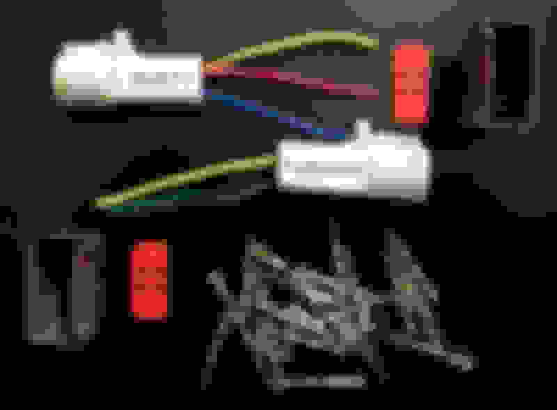
The remaining photos are procedural:
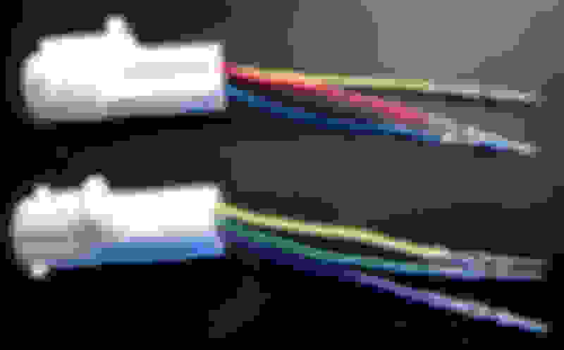
Note the wire coloring between the driver's side versus the passenger side. This wire color code remains consistent with all Ford Super Duties, but I still labeled my round shell connectors, just in case I forgot.
The white round connector shell mates to the what exists in the 99-01 doors. The grey rectangular connector is what is found in 2002-2007 doors, and mates to 2002-2007 mirrors.
The two red pieces are the terminal assurance retention devices for the yet to be terminaled grey connector shells... ie, the red things are the Wedges in Ford's Wedgelock wiring connector system.
Stripping and crimping comes first. It is critical to use a crimping die that folds over the open flags of the uncrimped terminal, such that the flags wrap over and dig through the center of the wire strands when fully crimped. The cable retention crimp over the wire insulation is a separate crimp operation. In this particular instance, I used "D" to pre crimp the bare wires, and "C" to cinch the insulation jacket wrap, and then "E" to fully crimp the bare wire crimp initially folded over with "D". We want to see a bit of bare copper peeking out on both sides of the bare wire crimp.
An automated machine crimp would wrap the flags around the insulation retention crimp, rather than dig the flags into it. However, in general, hand crimped terminals do not have the consistency of machine calibrated crimps, so I have no problem with the extra contact that the wire retention flags might make piercing through the skin of the insulation.
Because hand held crimps are generally not as reliable as calibrated mechanized crimps, I back my crimps up with just a little bit of solder wetting, limited to the wire to terminal contact area. I don't want solder wicking all the way up the wire, as that will make the wire to stiff and not resilient and flexible when wrangled and retained away from the window glass track in the door.
As the previous photo showed, I run a fairly hot (but temperature controlled) iron, to get the solder to wet through quickly and get that heat away again. Still, the insulation jacketing that Ford used in the doors is not high heat rated. To keep it from deforming, I use aluminum clothespin style heat sinks. I started with one, and then added second one once I observed how soft the wire jacketing really gets when heated.
These heat sinks really work. When placed to close to the point of solder, they actually interfere with wetting, pulling the heat off the very parts you want to wick the solder through. Another case of a good thing being too good sometimes.
All leads crimped and soldered, ready to insert into the 2002+ gray connector shells. I walked out to the truck, where the 2002 mirrors were already installed, to visually match pin for pin where each color went.
Terminals pins inserted, but before installing the red Wedge locks...
TEST, DON'T GUESS.
Every circuit worked, so in goes the red Wedge lock to keep the pins in place.
There's room in the grey shell to add 7 more circuits, for turning signals, running lights, defrost, and who knows, maybe a puddle light or a 360 degree camera system. Imagine having a 22 pin connector like the 2011's. I wouldn't know what to do with all the possibilities!
One more thing: You don't have to retain the white round connector shell like I did. Instead, you can cut the corresponding round connector shell off from the door wiring, socket terminals and all, because you will need to change the sex of the wire terminals in the door from female to male anyway. If you chose this route, then the male pins identified in my first photo above can be directly crimped to the wires you blunt cut and stripped inside the door, once the original white shell was cut off.
Personally, I like the round white shell better than the rectangular gray shell, because the round white shell is a SEALED design, whereas the rectangular gray shell is not. Plus, with the original white connector still on the door wiring, one can retain easy backward compatibility in case the new mirrors get clobbered... meaning one can always pick up a set of older 99-01 mirror take offs cheaply on Craigslist (because everyone wants to upgrade to the '08 up style) and plug and play them quickly back into the doors using the original connector sans the adapter.
Interesting project. Been looking into this for a week or two. I looked at my existing harness in my 03 and I have the grey rectangular plug already but as you pointed out all the accessories are not there. So what your saying is all I need is the pins to slide in the existing plugs in both doors route them thru the door and find the right source for the appropriate accessories? I would be interested in what kind of crimpers you use exactly.
So what your saying is all I need is the pins to slide in the existing plugs in both doors route them thru the door and find the right source for the appropriate accessories? Where can I get the pins?
That is correct.
If you add a Howitzer mounted between the parallel arms of your towing mirror, and wanted to add an electronic trigger control through your power mirror wiring harness, you could utilize an unused cavity in your 10 cavity grey connector shell by pinning the door harness side with these male pins:
You would also need to find the corresponding female socket pin to add to the corresponding unused cavity in the mirror harness connector shell.
More realistically, let's say you currently have the rounded mirrors.. but without the cool reflectorized LED running lamps and turn signals embedded in the side. And let's say you wish to upgrade to these mirrors which Ford offered until 2007. The harness connector to these fancier mirror assemblies have more circuits filling the 10 cavity connector, with all female socket pins.
In this instance, all you would need to do is add your wiring to the door, and terminate your wires with the male pins shown in the photo above, pull the red Wedge out of your door side mirror connector shell, snap in your newly wired male terminal pins to the cavities that correspond with the circuit function of the new mirrors, and you're done!
Search google or Amazon using any of the key words on the label in the photo to source the pins for purchase.
Help! Y2K, where do the gray conn come from? I have an 01, and just ordered the upgraded mirrors from A1. I looked on the Mouser site (from Tim's write up) but got totally lost. Just in case, do you have a part number for the Ford adapter you mentioned?
Thanks.
Tom, the Ford adapter would convert Early 99, 99, 99.5 and 2000 trucks with the white round connector to the rectangular grey connector that I *think* you already have in your 2001. Although, it could have been calendar year 2001, for model year 2002, that the connector changed. I'm starting to forget these details as time goes by and age takes hold.
The bigger question is, why didn't A1 ship you the adapter harness you need? If I were you, I'd message Tony at A1 and asked what shipped with your order if you haven't received it yet. You might be pleasantly surprised to find out that your kit comes with everything you need. (I have no personal experience with A1, as I just prefer OEM stock stuff). Check with Tony at A1 or 1A or whatever they call themselves before you scramble the jets looking for an adapter.
Great "How-To's" like this are often lost over the years because of bad web links, moved files, deleted accounts, etc. I've managed over the past 8-9 years to snag some of these threads and put them into PDF's which can be easily downloaded by fellow FTE members, and will do so again for this set of instructions. You see, I have a set of '08 take-offs which have the PF/PT functions, so I will certainly need this info later myself.
I'll also admit right up front that I've offered to do this before on some other threads and have not always gotten around to completing the task, but I have some skin in this one myself because of my take-offs which are awaiting an good installation effort (I am a selfish human, after all). It is key that my work load is very light right now. Consequently, this one is going to get completed and posted... perhaps even later today or tomorrow.
At this point, I've already downloaded this entire thread AND the ones from timf150 and Archion on the 08+ Install Upgrade details. To reduce the number of pages and file size, I'll clean up the image sizes and delete the extraneously repetitive signatures. I will also potentially delete generic posts which only add to the document length, but only if there is no critical information contained within those posts.
Once the cleanup is complete, I will post the composite PDF for everyone's easy reference and download. I will also include web links to all important details (including the threads), and I will make sure that folks get credit for their inputs. I'm just a facilitator, and want no credit for any of this work.
I'm going to submit the above referenced PDF's in a separate and new thread just so that when someone searches for this type of information, they can find the new thread and all the pertinent PDF attachments will be at the beginning of the thread for easy locating.
Thanks. Well, I probably out smarted myself with A1 because I ordered for an 05 so I wouldn't have to answer the "it won't work" questions. I am not sure what mine look like (round or rect) but I will peek this weekend. Mine is a Jan 01 build. Seems more folks go for the 08 and later, or just splice the wires in, but I like the idea of making it as factory as possible. Will see. Will report back on what happens.
Just a quick update, I do not have the rectangle connector. Mine is round, and somewhere in my reading I saw after a Feb 2001 build date they switched. Mine is a Jan build. Darn it. Pins are ordered from "Clips and Fasteners", now need to find the time to chase down the gray connector. Mirrors from A1 are great, mounted the drivers side, no vibration.
Great job on the write up and photos are excellent !! Also I like how you handled all the little details in a very professional manner.
First class work !!

 11-09-2015, 02:24 AM