When you click on links to various merchants on this site and make a purchase, this can result in this site earning a commission. Affiliate programs and affiliations include, but are not limited to, the eBay Partner Network.
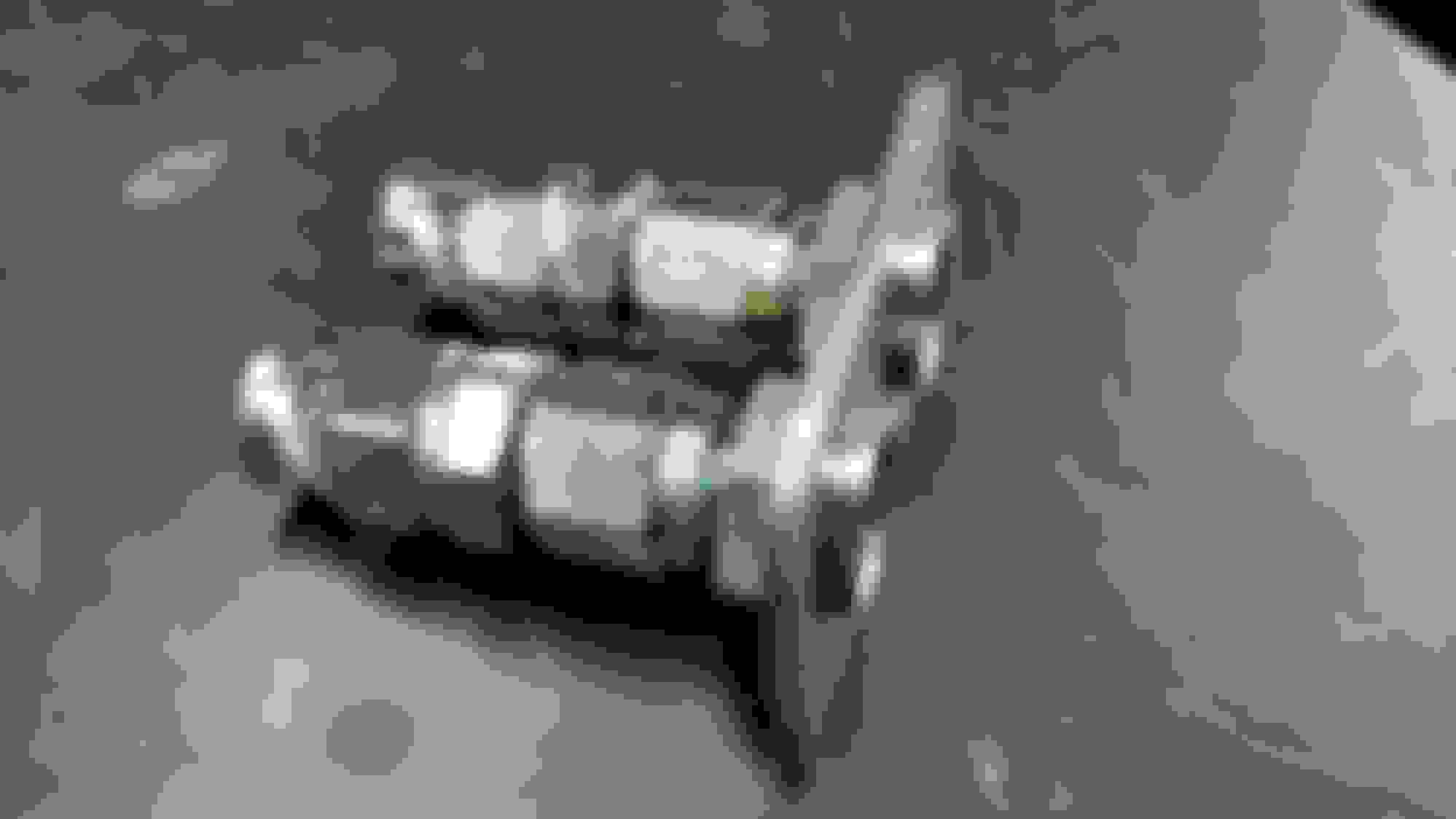
Since my last post Ive been gathering plumbing fittings for the rear fuel lines and got that section installed. I decided to mount my fuel filter and charcoal canister in the area behind the rear axle. There is a big wasted space there and it will keep the frame rails cleaner. It will also be easy to access the filter for service.
I made a package tray out of some 1 1/2" square stock, 1/8" plate and some angle iron. I mounted it to my shock mount tube. I used my notcher to drill out a hole in the square stock then cut out a slot to slide over the sway bar tube. This bracket is a permanent mount with the parts bolted to it.
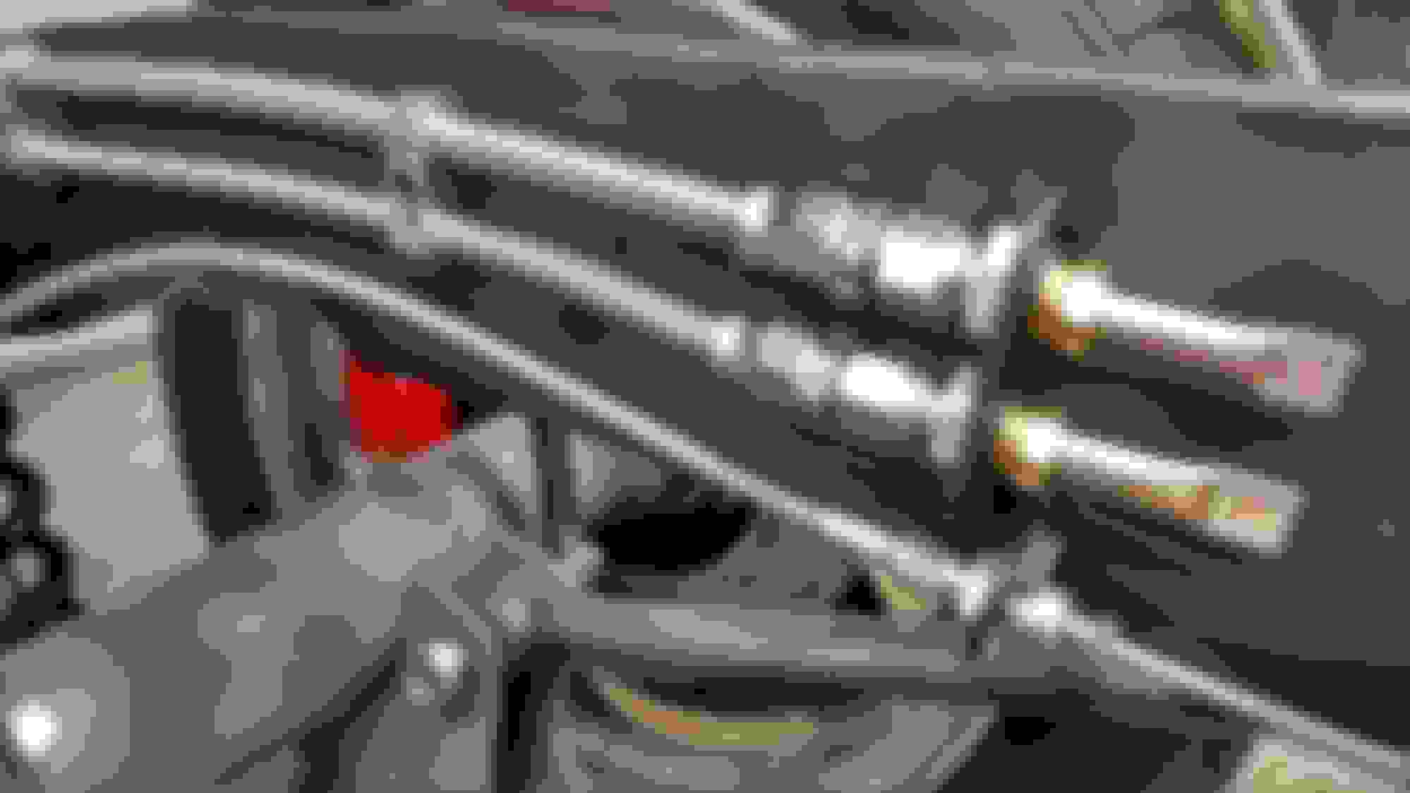
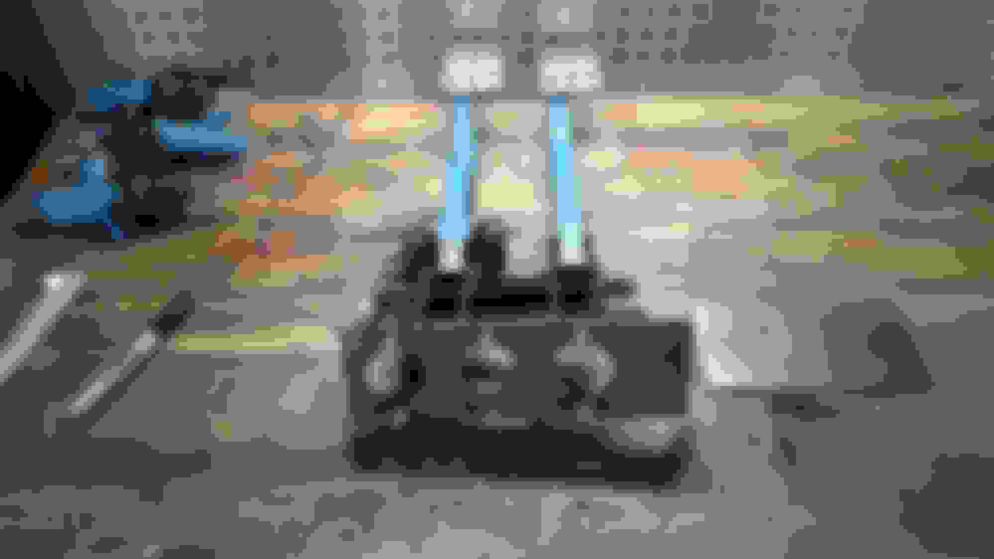
I'm running -6 AN flexible line from the fuel pump to the filter and to the frame. From there l'll run 3/8" pressure and return hard line down the frame rail. I'm using PTFE lined braided hose. PTFE is a fancy word for Teflon. These lines last indefinitely and no worries about rubber deteriorating and clogging the injectors. It is more expensive, but it's install and forget. Same stuff they use on OEM. It is also less bulky than rubber lined. It looks like this.
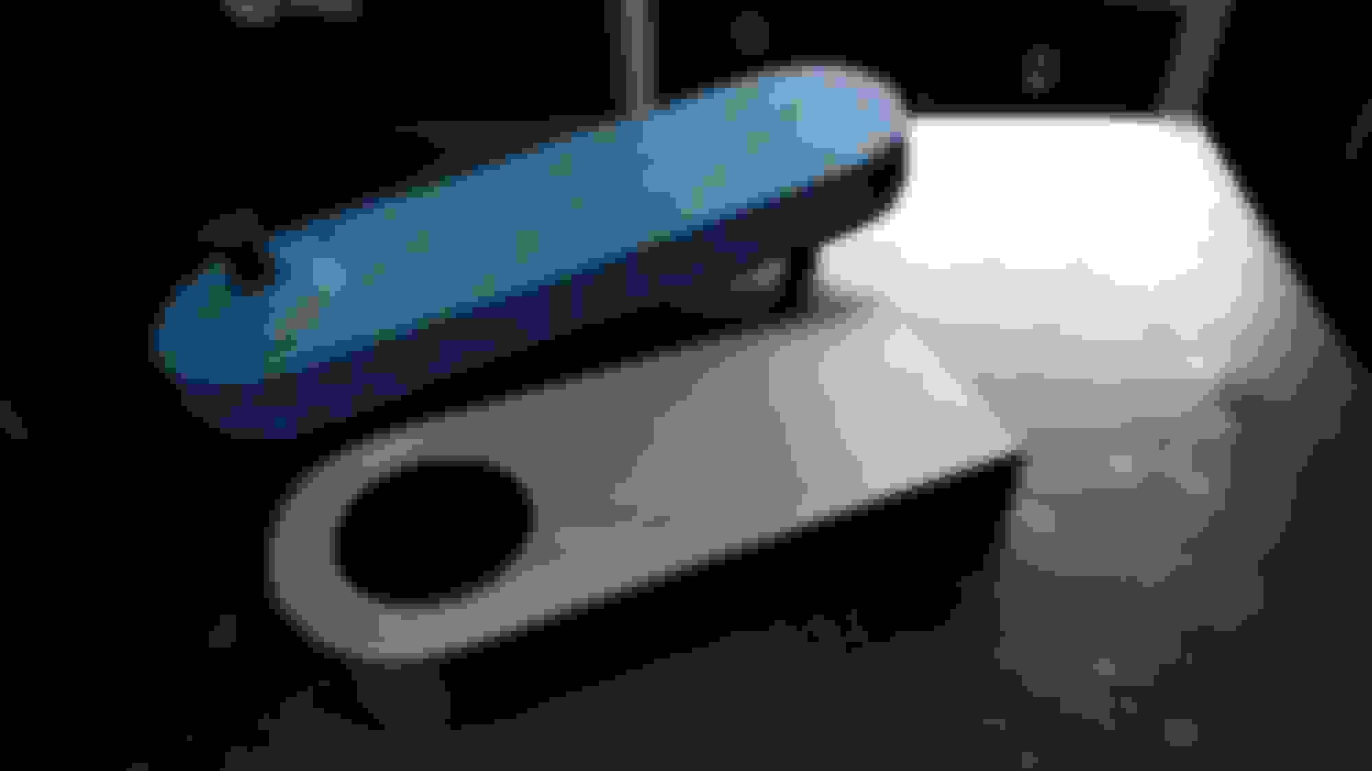
Then I made up some lines. I noticed during mock up that the return line will be close to the bed mount slat, so I slid on a thick rubber heat shrink tube for protection before I installed the ends. I think I poked my fingers with the braid enough times for one day lol. All the fittings and hose is summit brand. Its about half the cost of Earls or Areoquip and always worked well in the past for me. I like just plain silver but they have colors too.
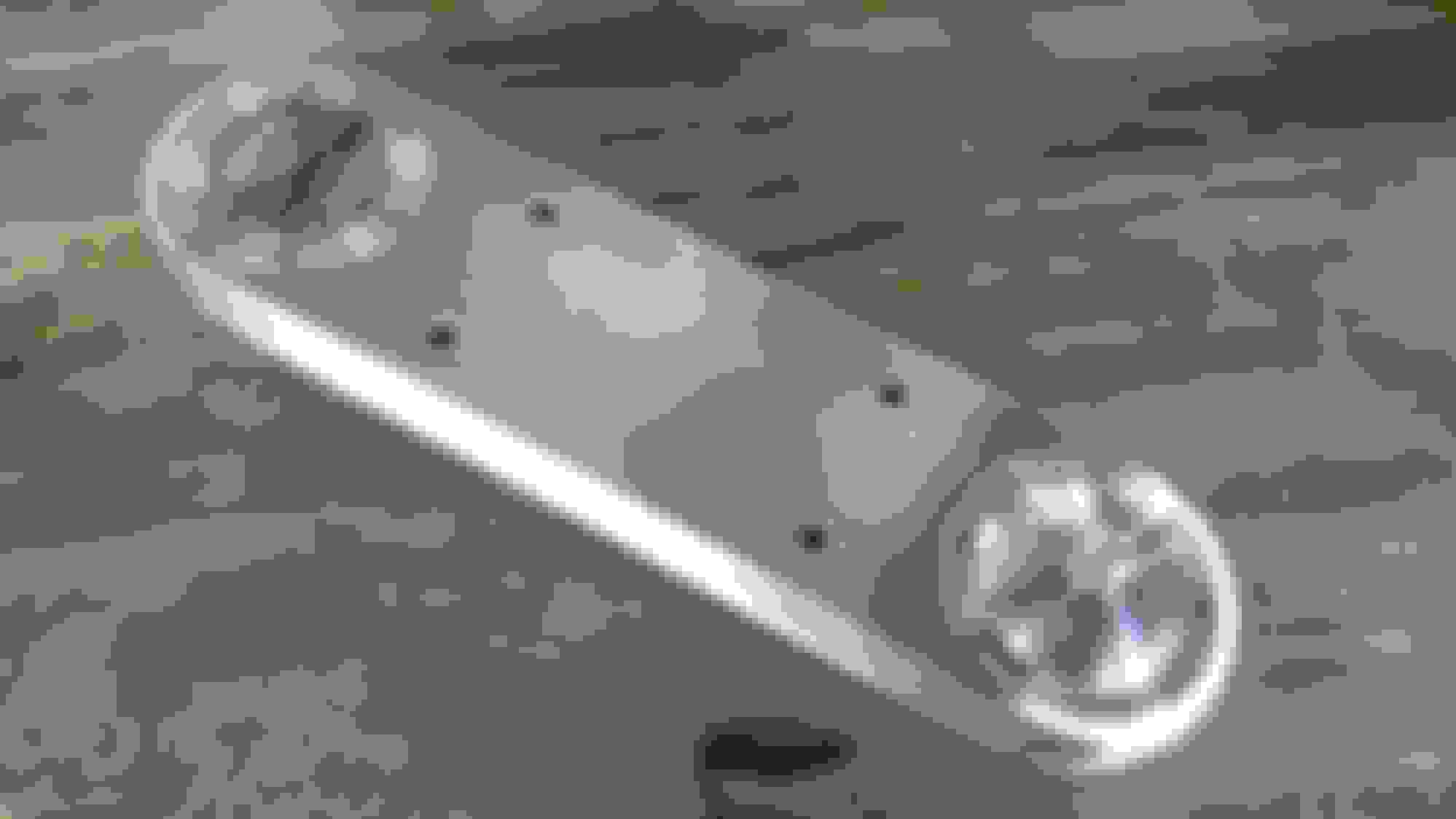
Im going to secure the fuel line to the frame with wire seperators. Rather than just drill and tap threads in the relatively thin frame material I used Time-sert thread repairs. These work good for repairing stripped threads as well as attachment points. The kit consists of a drill bit for the initial hole. Then a countersink bit that sets the flared lip on the time-sert flush with the surface, then a tap for the fitting and an installation tool. The installation tool locks the fitting in. They are handy.
They look like this installed. I used two on the frame rail and one on the shock tube. Now I have nice threads for the mounts with no worry about stripping out.
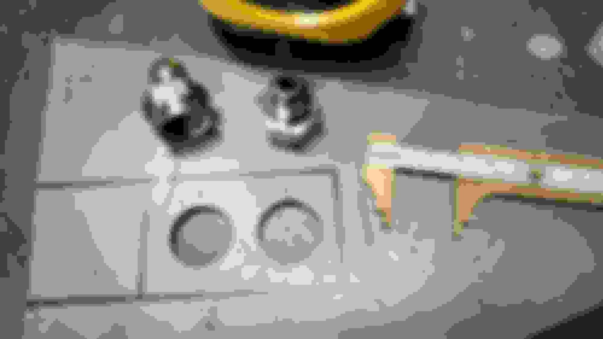
To dead end the AN hose on the frame I made a bracket that will attach to the frame.
Then I cut it out and tacked in the fittings. These fitting are -6 AN to 3/8" NPT inverted flare.
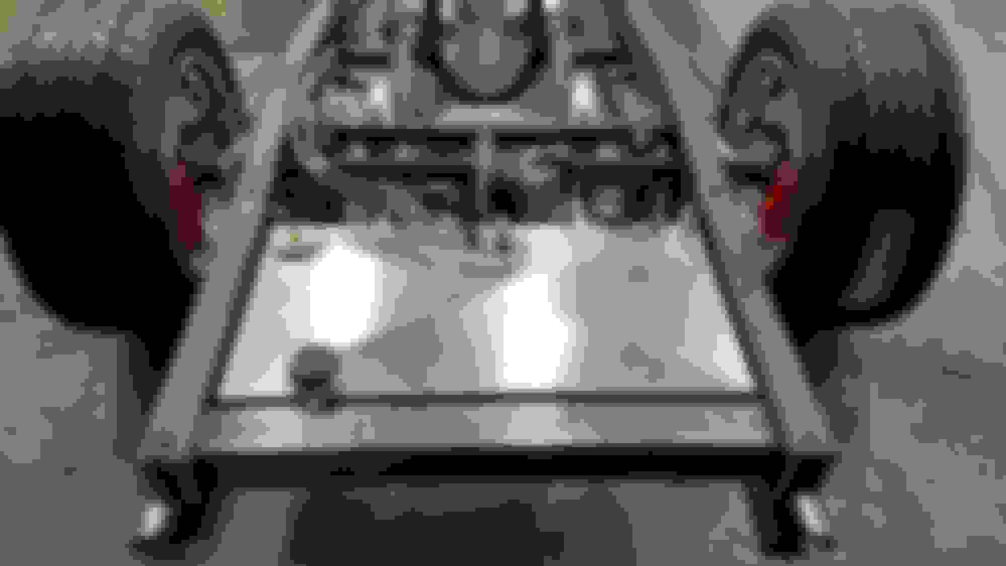
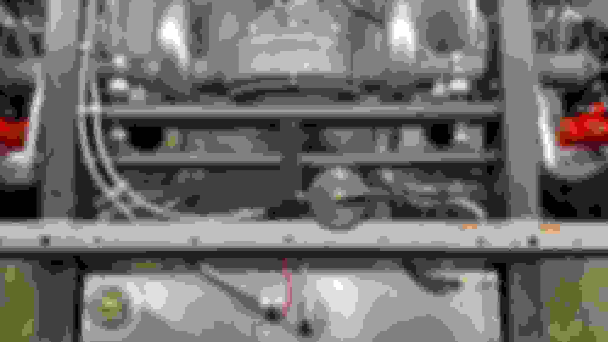
Then I installed the lines, mount brackets and vapor can.
Here it is with the bed slat. I had to notch it a little. I'll weld a reinforcement plate under neath next.
This it the fitting bracket welded to the frame. The lines on both ends are removable, just the center fittings are welded to the bracket. I put some temporary line in them and squished it closed to keep out junk.
I'm not going to run the line down the frame until I have the front sections figured out. A few little things to button up, then the cab goes back on and I'll start on the pedals and steering.
OK starting to go through some withdrawals here. We need some updates Nick!
Lol. Thanks fellers.
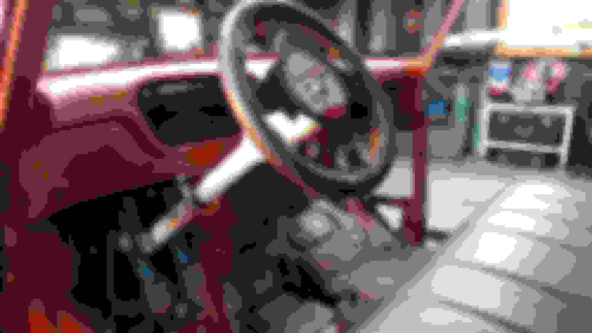
I've been pondering the bench/bucket debate. I really needed to finalize the seating position so I could move on to the steering and pedals. I decided bench. So I did a final pedal and column mock up. I was going to lower the seat, but that just opened a giant can of crap as the pedals and column ended up in funky positions. The steering wheel also ended up blocking the gauges. So stock seat height it is.
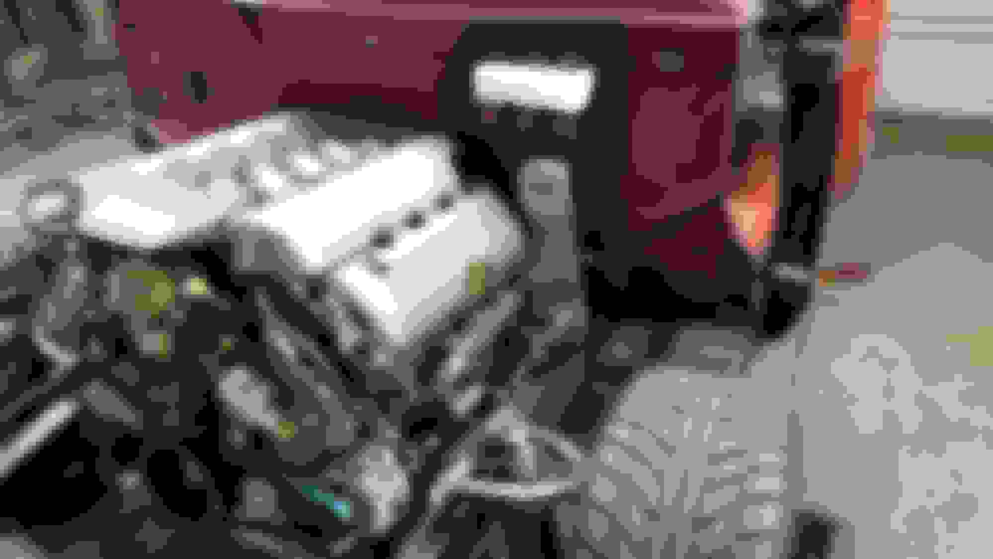
With that done, I know the cab entry point for the steering shaft. I moved on to the electric power steering. As most know the 2015+ Coyote engines don't come with hydraulic power steering mounts as the production car has electric PS. There are many after market ways to mount hydraulic PS. In my planning the hydraulic accessory kits + PS rack + lines + pump + aftermarket AC compressor is very close in price to going with electric ps, manual rack, and ford AC compressor. So I went electric.
This is my first go with electric PS. I went with a kit from UniSteer. They offer several size kits for different weight vehicles. I went with the largest which is a 360 watt kit. It is good for vehicles up to 4,500 lbs. They offer two styles, a universal kit and also a kit that mounts mid way in a standard 2" column. I went with the universal. Under dash space is too limited.
It comes with small "brain" and I opted for the extra dash control. It is just a **** that can adjust the assist as I please. From none to full. The motor assembly has a torque sensor and applies more assist when more torque is sensed. The **** sets the limits for the sensor.
It looks like this:
The unit comes with a universal mount plate. It is 1/8" steel. It wouldn't work in my application, but it did make a handy template. With the engine in, and cab on I found a spot to mount the motor assembly. Space is tight here as the coyote is wide, but I found a good spot. I need to account for exhaust clearance to the electric motor, u joint angles and cab entry. I built a make shift support to hold the unit. Then pulled the cab and motor for room to work. The make shift mount just helps me be sure it hasn't moved from the position I need.
With the electric motor assembly supported I made a bracket to mount it. I used 3/16" steel plate and used the supplied template to drill the holes.
The mounting plate gets sandwiched between the motor assembly and the shaft bearing/dust seal cap with three bolts.
I welded the plate to the frame between the engine mount ears. Then added a gusset on top. Later when I do the final strip down and frame finishing I'll also weld a gusset on the bottom.
I designed the mount so the electric motor assembly can be service from underneath the truck in case It ever has an issue. Then I reinstalled the engine and mounted the assembly.
Can't see much of it with the engine back in, but its there. I talked to the guys at UniSteer prior to install. They suggested a minimum of 4" between the header and the electric motor. I have more than that, but will probably add a heat shield later.
Next is the Wizard steer clear, column, and pedal assembly install. I have some sheet metal work to do on the floor plan for the column and the bulkhead for the pedals. Then I can measure up and order a custom column.
I've been working on the steering and pedals. I took a long time playing around with pedal placement and steering wheel position until I was happy with everything. To make test runs with the pedals I cut a large hole in the bulkhead. This section needed to be cut out anyway as I need the section flat to mount the pedals. The factory stamping had two parallel raised sections.
I made two templates for the pedal mount. One I fully drilled out and mounted to the pedals. Then I could c-clamp it in the large cut out and move the pedals around until I was happy. The other I just drilled out with an 1/8" bit. I'll use that later to drill the holes in the modified bulkhead. Once I was happy with everything I marked the firewall.
While I was working on the pedals I was also working on the steering. There isn't much room for error here as everything will be close. So it was a back and forth between the two until I got them to fit correct. For the steering I decided I wanted the column at a more horizontal angle. I have big feet and didn't want the column in the way of them. To do this I used a Wizard Steer Clear.
The Steer Clear needs to be frenched into the bulkhead. There isn't enough clearance with the engine to mount on the engine side, and if mounted inside the cab the pedals hit it and it limits the pedal travel. So I made a pocket for it that I will french into the bulkhead.
Once I was happy with everything I cut a patch panel from 16 gauge.
I welded it in and cleaned it up. Then transfered my marks. I tacked the temate I mentioned earlier so it didn't move at all. There is very little room for error as the master cylinder holes are very close to the mounting holes.
I welded in the steer clear pocket and drilled out the pedal holes.
Hit up with some primer.
Then I mounted the pedals and steer clear. Everything lines up well. The steer clear is sunken about half way into the bulkhead.
Then the cab goes back on, seat back in and I check it over for comfort. Everything is just how I wanted. The pedal height is perfect. I centered the column and can see the guage opening fully through the steering wheel. I offset the pedals to the left as far as possible so the brake is nearly under the column. All my u joint angles are under 30�.
Next I'll make some braces and supports for the pedals and steer clear. Also I'll close up the access hole under the pedals as I have no need for it. Then I can order up my column and wheel.
Looks great Nick! Thanks for the update I do look forward to them! Have you decided on the TCI seat yet? Which one are you looking at? I'm pretty much decided that I'll be putting one of them into my cab as well. Just not sure which model and colors yet.
Nick, I'm looking for the oil adapter, the new one. # M-6881-M50A for the 2015/2016 Coyote engine. I thought you mentioned it previously. Ford Racing say's it's not available, due to a re-design. Have you started your engine? Are you using this part? How did the Moroso oil pan fit?
 03-23-2016, 07:44 AM