When you click on links to various merchants on this site and make a purchase, this can result in this site earning a commission. Affiliate programs and affiliations include, but are not limited to, the eBay Partner Network.
I have the latest edition of Auto Enginuity and was wondering if im missing something with regards to Cylinder Change Rotational Velocity test? I set up all 8 cylinders ob the program and they never change from 0.00. Even if im driving around or sitting still at idle. Is there a special thing that has to be done to get it to show up?
I have tried that a few times. I have read that setting it up as a 2001 instead of late 99 might help. I also read that since I have a dp tuner it may not work. I am going to keep trying. I would like to check the two cylinders I had set codes during cct.
What is your idle speed when trying to pull it up in the "live data meter"? You will only see these values while idling and if the idle is set higher then it will read zero as well.
The oil temp has to be above a certain number before you can see the PERDEL figures. Engine also has to be at idle with A/C turned off.....you can be in drive if you like (with your foot on the brake)--4R100 models only of course...
I have tried to do it in stock setting. I'm not sure on the idle speed, just above 100-150 rpms? I am going to try again tomorrow when the truck is warmed up after work. Cylinders 2 and 8 show up in the cct but 1 and 8 show up on the buzz test codes. It seems to run alright but keeps pulling the codes.
This morning I went out and the truck started right up and had a decent idle. I ran buzz test which failed #1 and # 8 and I shut off see light. I drove to work just missing a little. Cyl #8 and Cyl #2 fail CCT. I am hoping when I replace the #8 injector the light will stop coming on. Do you think that its the cyl #8 injector that is causing the light? Failed CCT and buzz on #8? Tonight I will try perdel again.
When I just run DTC test I get P1316. When I run buzz test I get P1268 and P1271. When I run CCT I get P0266 and P0284. If I clear codes sometimes only P0284 will come back with CCT.
When I just run DTC test I get P1316. When I run buzz test I get P1268 and P1271. When I run CCT I get P0266 and P0284. If I clear codes sometimes only P0284 will come back with CCT.
Sounds like it is time to grab a multimeter and do some ohm testing through the 42 pin connector on the drivers side valve cover.
Here are your trouble codes:
P1316 Injector Circuit/IDM Codes Detected
P1268 High to Low Side Short - Cylinder 8
P1271 High to Low Side Open - Cylinder 1
How did the injectors sound during the buzz test? Can you give us an audio or video file to look at? Did 1 and 8 sound noticeably different than the others?
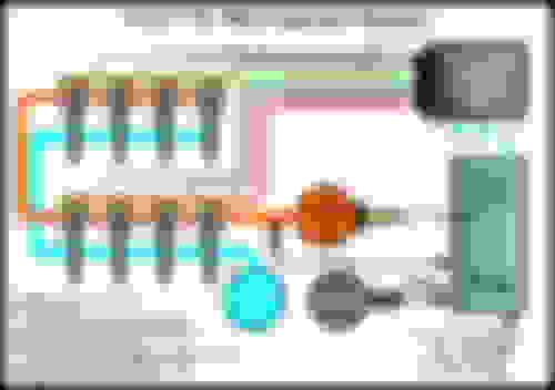
The injectors are grouped into two banks of four injectors each -Drivers side & passenger side. Each bank/side shares a common power feed which is generated by the IDM. The voltage supplied to the injectors is 115 volts DC and is only activated when one of the injectors is firing.
The injectors have 8 individual ground circuits. An injection event occurs when the IDM supplies power to the bank for the injector to be fired while simultaneously grounding the desired injector’s ground circuit.
So, I would check your wiring (which is easy to do) from the 42 pin connector to the injectors & back before pulling injectors. The codes are pointing to a short in #8 on the drivers side and an open circuit to #1 on the passenger side. This could be a wiring/electrical problem.
Here's something that Rich(Tugly) & Pete(F250_) put together to help troubleshoot the IDM & wiring. Basically you need to:
Clear out the trouble codes
Run a KOEO test and recheck for codes
Injector buzz test - see if any sound different from the rest.
Unplug the 42 pin connector on the drivers side valve cover
Ohm out injectors at the 42 pin connector, this will test the wiring from the 42 pin connector to the injectors and back (including the UVC wiring harness). Ohm test between the drivers side + supply & the even number injectors pins in the pic below. Then ohm test the passenger side + supply and the odd number injector pins in the pic below.

 04-09-2015, 03:09 PM