When you click on links to various merchants on this site and make a purchase, this can result in this site earning a commission. Affiliate programs and affiliations include, but are not limited to, the eBay Partner Network.
Fantastic build of an excellent truck! You did what several of use preach which is to buy the truck with the best sheet metal that you can find since that will be the quickest and least expensive route (and you have the best truck in the end).
From the one picture of the mocked up firewall it looks like you will need to modify the firewall some to open up the cutout at the center where the stock transmission pan screws to. Is that the case or is it just the angle of the photo?
Just the angle. I found out a couple days ago everything worked as planned, no cutting necessary and had some room to spare.
I loved seeing how you removed the cab. This will be a huge help to me. I'm strarting on my '52 this week. I have no family to help me get the cab off and your photo has helped me tremendously.
I loved seeing how you removed the cab. This will be a huge help to me. I'm strarting on my '52 this week. I have no family to help me get the cab off and your photo has helped me tremendously.
Well, doggone it. Welcome to FTE!
If you hang around here, you'll see there are lots of folks with knowledge and advice to share. I'm not one of them, but I have learned an awful lot (and still learning) from the guys on this forum.
Please start a build thread and SHOW US PICTURES! They feed our addiction, and we need a fix.
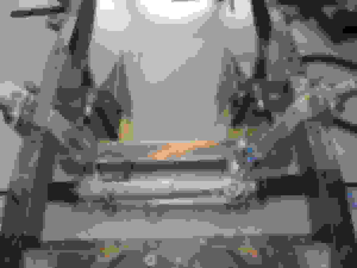
Update on the work on Belle. Mostly checking for fit, final welding and cleaning in preparation for painting.
Checking the TCI custom IFS for fit
I checked the track width after installation, 60" OC same as before.
Spraying weld through primer before installing the boxing plates.
TCI sent boxing plates for a 53-56 truck instead of a 52. TCI customer service is useless when it comes to after sale help. Since we cut the boxing plates in half anyway we just re-cut the front half to fit.
I had the right boxing plate bent to clear the exhaust. Both plates and the cross member were fully welded later.
Before work began we noticed the bumper was noticeably low on the drivers side. When I leveled the frame and measured I found the left frame rail dropped about 3/8" from the radiator cross member forward.
I cut the left frame rail at the front spring mount hole and lifted it till both sides were the same.
Filler plugs were machined and welded into both sides. Here fitting on the passenger side.
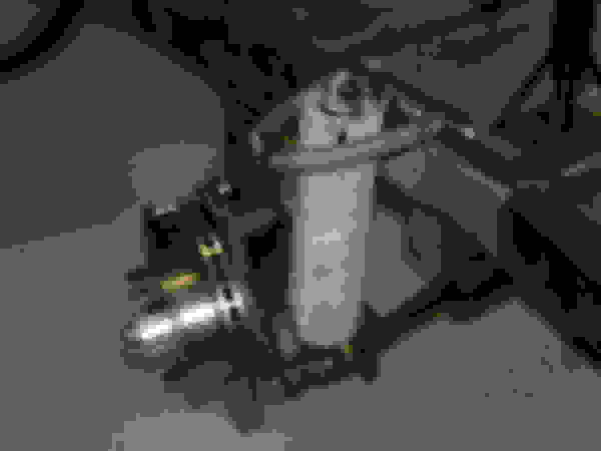
I cut the frame side of the mounts for a good fit between the engine mount and frame.
The engine and transmission were positioned carefully and wired in place so I could lay on my back and tack the mounts in place without worrying about movement.
Because the cross member was wider than the frame it hung over each frame rail by 1". Rick made a set of 3/16" plates that were welded between the overhanging
cross member and the outside of the frame.
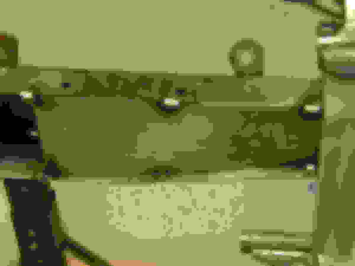
Cross member boxed on the outside of the frame. Alternator has 1/4" clearance.
Cross member half welded.
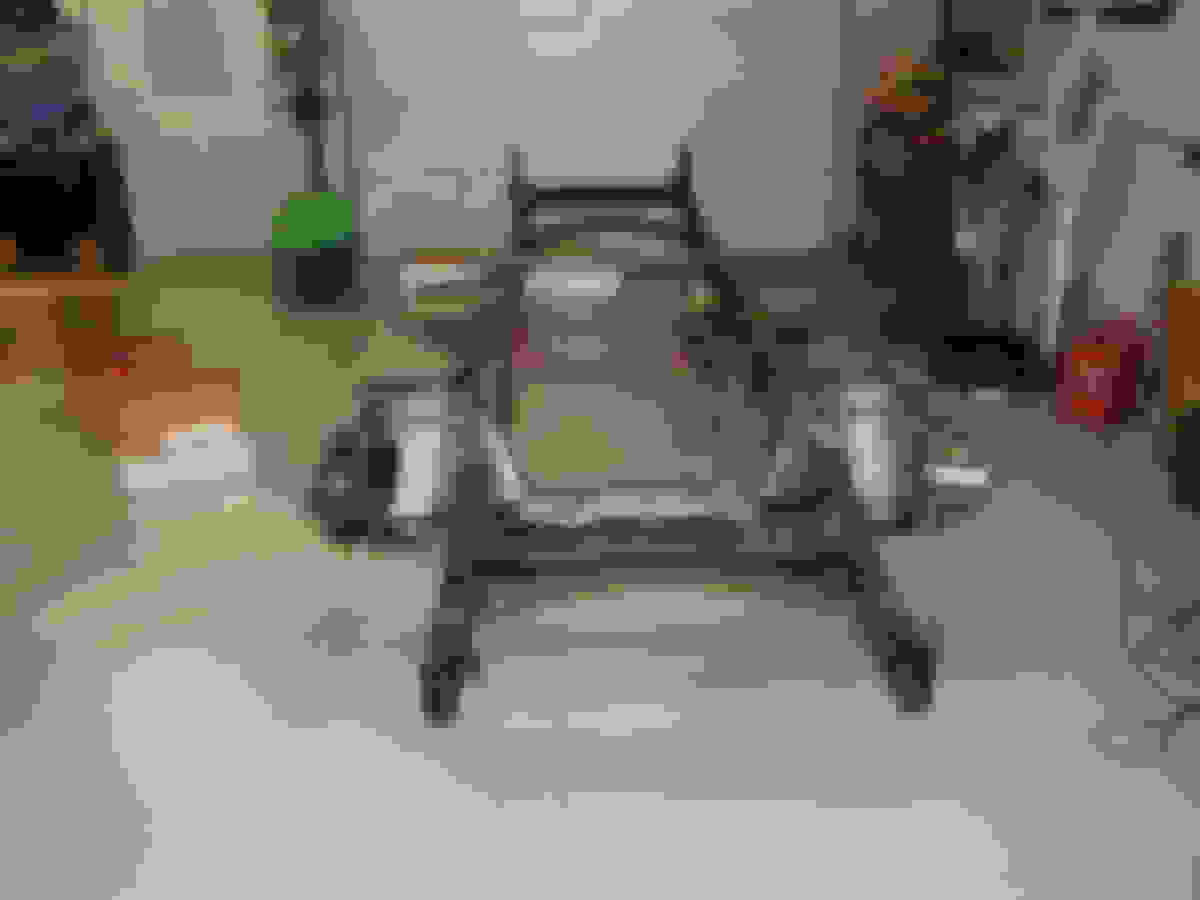
All welded except the bottom side. I will do that when Lois and I flip the frame.
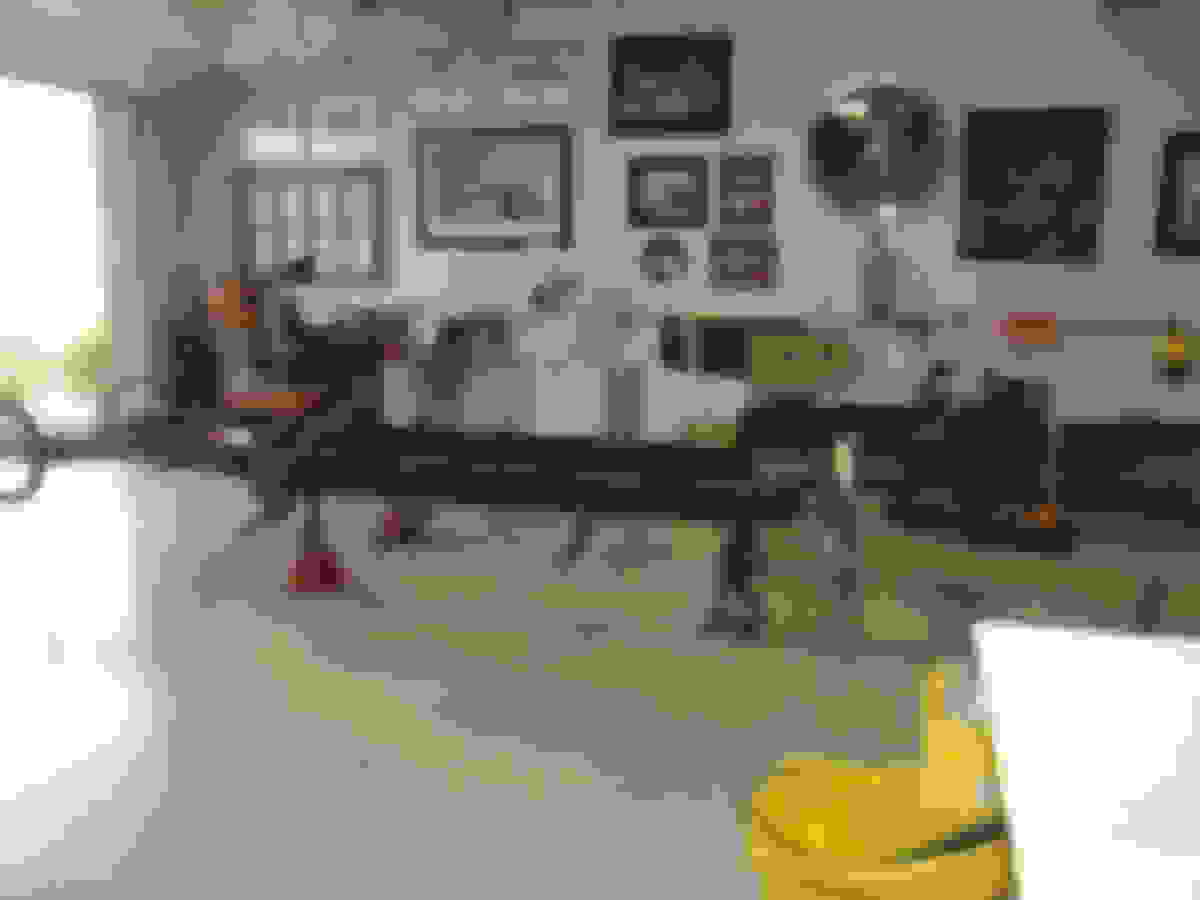
Welding done and Lois
cleaning for paint. Frame is still upside down after I finished welding.
Frame cleaned. Right after this a friend came over and could not believe the condition. Then he told me he had a sand blaster and I should borrow it and blast the frame. That will be next.
Close up of the cross member and the outside boxing plates. The good welds are Rick's and the others are mine, not the most beautiful but good penetration and strong.
Mike,,,, don't you love the TCI custom IFS? I sure do! That wasn't available when I ordered my TCI frame. I just ordered another frame, with the Custom IFS for a buddy of mine, for his 50 F1.
Mike,
You are making great progress. There are very few of us I suspect that have help from our wives/significant others!
Very nice fit up work on the IFS/engine/exhaust. Do you plan to add an additional crossmember behind the transmission to replace the frame twist resistance lost by cutting the original transmission cross member? In my case I moved the original transmission crossmember back about a foot, however when I did that I needed to add a master cylinder mount.
Mike,,,, don't you love the TCI custom IFS? I sure do! That wasn't available when I ordered my TCI frame. I just ordered another frame, with the Custom IFS for a buddy of mine, for his 50 F1.
What are you painting the frame with, PQR-15?
Your project is looking great
Mark
Mark, I actually bought the suspension back in 2013 when they had a sale and yes it sure is nice. Frame will be epoxy primed then painted with Eastwood 2K ceramic black.
Mike,
You are making great progress. There are very few of us I suspect that have help from our wives/significant others!
Very nice fit up work on the IFS/engine/exhaust. Do you plan to add an additional crossmember behind the transmission to replace the frame twist resistance lost by cutting the original transmission cross member? In my case I moved the original transmission crossmember back about a foot, however when I did that I needed to add a master cylinder mount.
Bill, it is nice that Lois helps out, she always has. The next installment has the fabrication of a new cross member. As the frame is in the last photo when you put weight on the running board mounts you can see the frame really bow on the middle.
My wife wanted to retain the stock steering wheel and column on Belle. Because we are changing to rack and pinion steering we would need to install a u-joint on the end of the column. This is no problem as CPP makes a kit to do this and I have seen it done on this site several times. When you do this you can no longer use the wheel mounted horn button as the wire can no longer exit through the bottom of the steering box. I spent some time this weekend solving that problem.
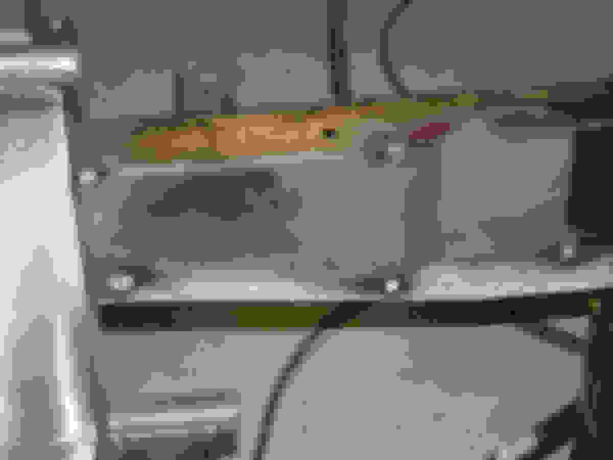
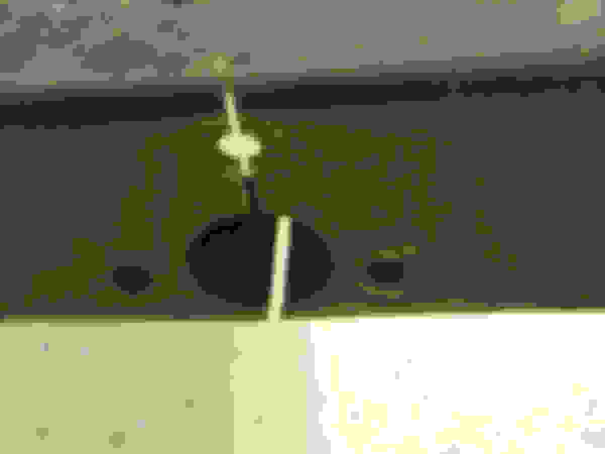
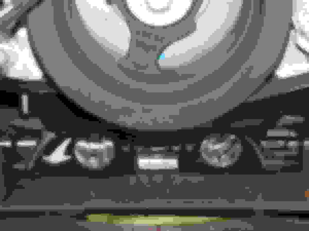
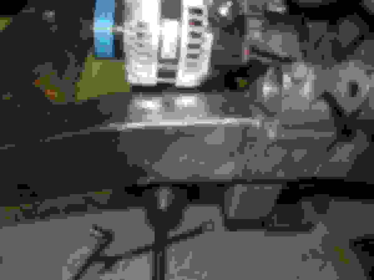
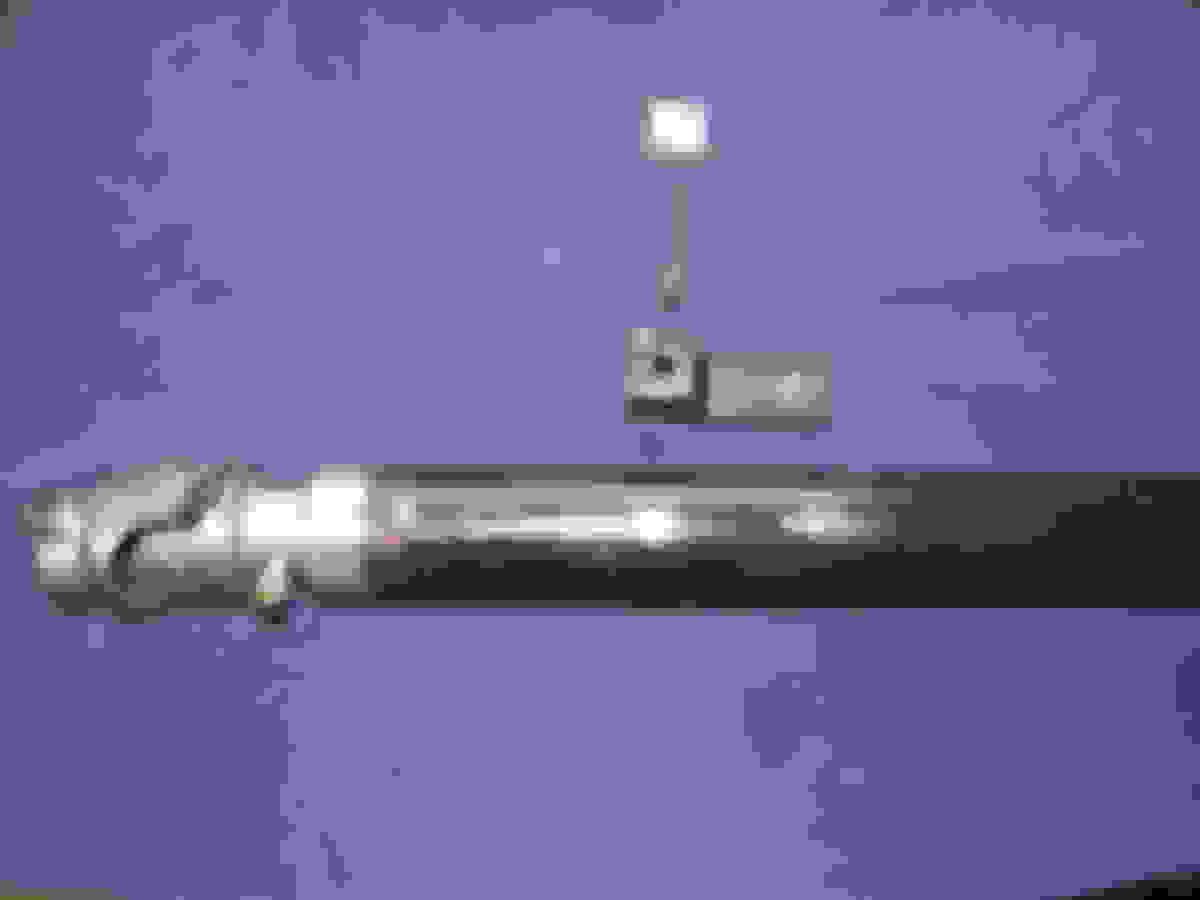
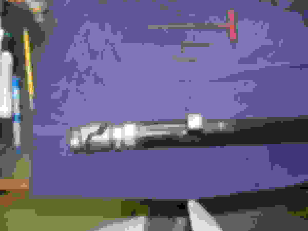
Here are all the components of the column. The tube has been cut to the correct length. A hole has been drilled in it for a electric motor brush to pass through and a nutset installed to retain a delrin brush holder Rick made for me. The original shaft has a u-joint installed then the CPP column saver. Further up the shaft is a delrin bushing with a bronze bushing on the outside. I pressed the bronze and delrin bushing onto the shaft, friction holds them in place. I then drilled a hole through the shaft and soldered the horn button wire to the bronze bushing, the wire and bushing are now insulated from the rest of the column. The brush holder being delrin also insulates the brus and spring from the column. The metal cover will have a wire installed under one of the two screws and this will attach to the ground side of a horn relay. When you press the horn button ground current will travel down the horn wire to the bronze bushing. From there it flows through the brush and spring to the metal cover and finally the horn relay. Checked it with a OHM meter today and it woks great.
All the components need to make the horn work.There is a delrin sleeve between the bronze bushing and the steering shaft to keep it electrically insulated.
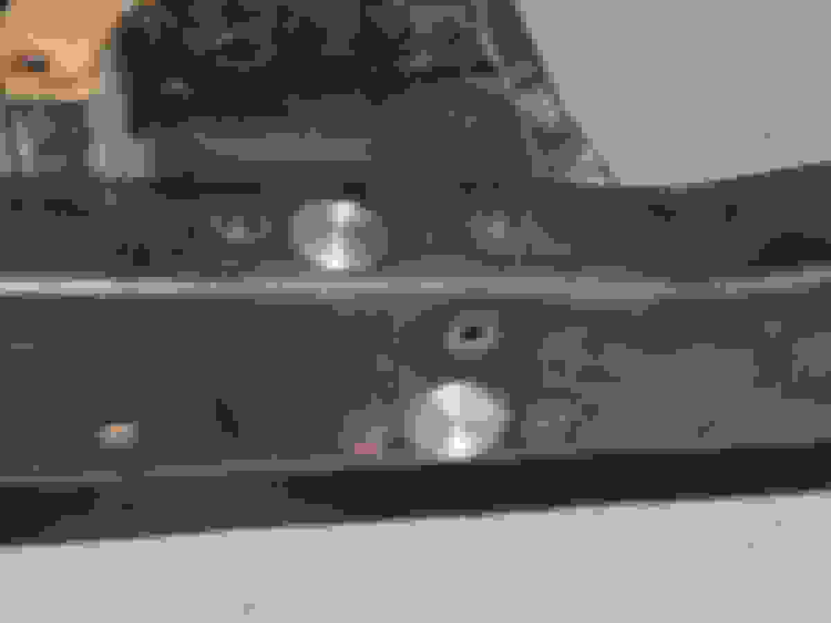
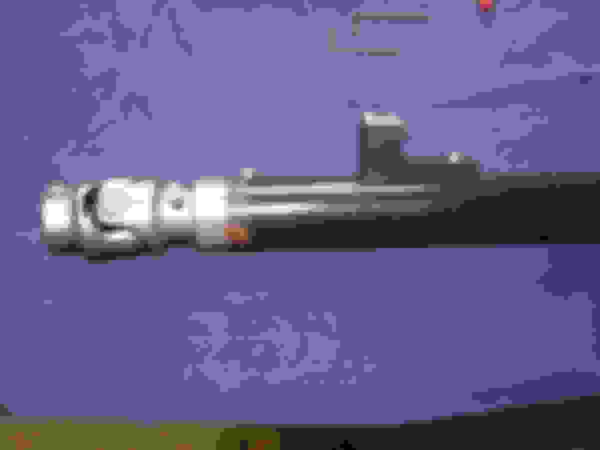
You can see the bronze bushing inside the hole in the steering tube.
The delrin brush holder is installed. The brush and spring dropped in the hole and the cover installed.
As seen from the side . Column will be installed so this on the top side out of view.

 01-04-2015, 10:23 AM