When you click on links to various merchants on this site and make a purchase, this can result in this site earning a commission. Affiliate programs and affiliations include, but are not limited to, the eBay Partner Network.
Hopefully, the compressor won't give you any issues in the future. I think it looks a lot better down there. Cleans up to top area. Good work.
We shall see. Given the way that the Vintage Air "sure fit" system routes the hoses out the passenger side fresh air intake panel and along the inside of the passenger side inner fender it will certainly shorten the hoses and hide them a bit. It feels good to have a fallback plan should this not work out for some reason. Obviously, I am not the first so there is that assurance.
I'm not sure if it was on the F series 2wd or not but my 78 Bronco had a rubber splash apron from the radiator support to the frame to keep the splash and junk off the low mount alternator. May be good for the low mount compressor.
My overall objective right now is to prepare this vehicle for first start and break-in of the power train. Thus, I will be working on a list of items that are all related to this goal but not obviously or necessarily to one another. Removing the speedometer cable and replacing it with a digital sensor is one of those details.
Installing the entire Dakota Digital Dash system will probably be done in several installments, most of it after the cab paint and body work is all done. For now, getting the old speedometer cable out of the way is a good thing to do but that wasn�t accomplished without some difficulty.
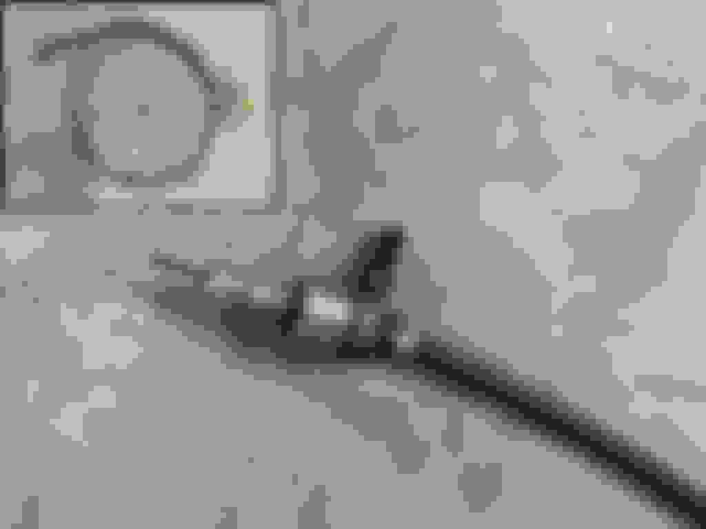
The first step is to remove the original speedometer cable and salvage the plastic gear and its retaining clip for use with the new digital system. Note the close-up of the transmission end and the curvature of the retaining piece. It is different from what Dakota Digital provides.
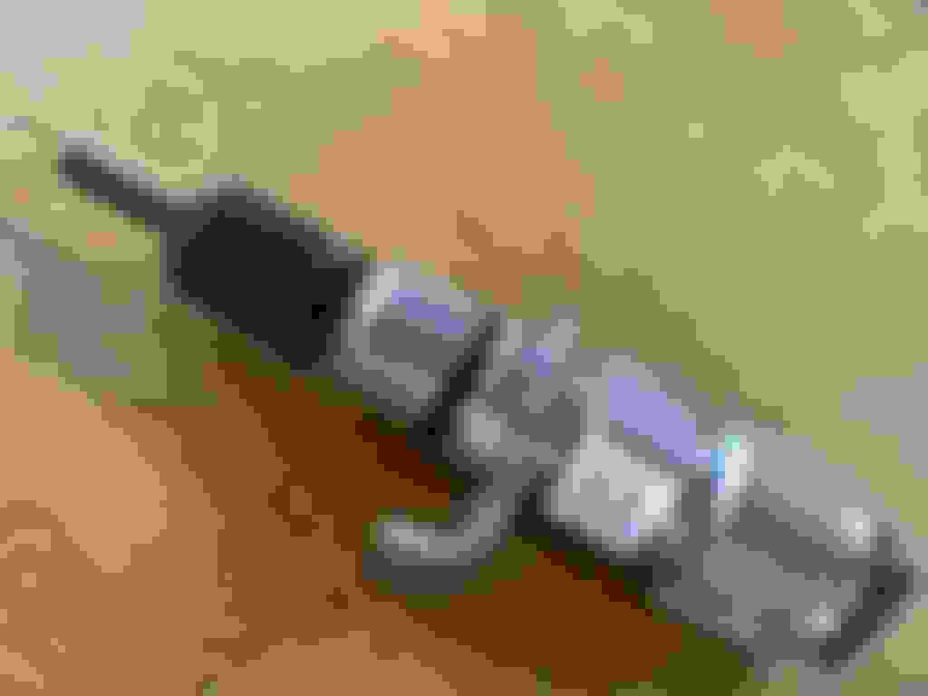
Here I have added the original speedo gear and clip to the Dakota Digital adapter. To its right is the digital sensor that attaches to it. I had to reduce the curvature of the adapter retainer in order to get all of these pieces to play well together.
Here they are together away from the transmission but it was not possible to attach all of this to the transmission properly because of the retainer causing the retaining bolt to interfere with fully seating the sensor.
Reshaping the retainer as shown here allowed the retaining bolt to sit below the threads for the sensor.
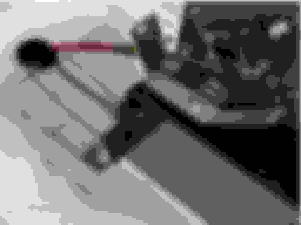
So here they both are attached to the transmission. Note the closeness of the adapter retaining nut and the sensor. It�s all as tight as it should be but it is close. I was unable to use a 7/16� box end wrench here. Only an open end wrench would do. The adapter has to be attached tightly first and only then can the sensor be properly attached to the adapter.
Next up will be selected from the following:
Develop a temporary exhaust system with muffler. The final exhaust system design has a number of issues yet to be resolved so temp will have to do for now.
Implement the temporary wiring plan described earlier. Obviously a pre-requisite to engine break-in and power train testing. The full rewiring will be done after cab paint and body work.
Support rear axle for testing. Wheels will need to spin smoothly.
Assure emergency and hydraulic braking system functionality necessary to transmission testing.
Implement basic functions of floor shifter to enable transmission testing.
The work toward first start and break-in of the new engine, transmission and rear axle continues. Having a way to select the gears in the new TCI StreetFighter C-6 transmission will be an important part of its break-in procedure so that function needs to be taken care of. As indicated previously, I acquired a B&M Megashifter for trucks during my period of involuntary absence due to family exigencies. So the time has come where I will need to install and adjust this piece of equipment. The time is not perfect because I may be exchanging the bench seat for buckets at some point in the near future and that is an important consideration in placement but the need to maintain momentum overrides that. The hope is that luck will be with me.
Here is what I found in the box for the B&M Light Truck Megashifter (part number 80680). It will work with Ford, GM and Chrysler vehicles so there are many parts here that I will not be using. As well, certain applications will require additional kits. For Ford trucks with C-4, C-5 or C-6 transmissions, no additional equipment is needed.
My first step was to create a center line where the shifter will be mounted. Because I plan to swap the bench seat for buckets of some sort I ignored the directions that called for pulling the bench seat as far forward as possible. At 6’-2” I normally have the seat as far back as possible anyway.
I assembled the framework as high as possible in order to position the unit by matching the center of the plastic surround with the centerline of the cab transmission tunnel.
Removing the surround I was able to mark where the mounting brackets met the transmission tunnel and drill the two 5/16” bolt holes in the flattest part of the tunnel.
1/4-20 X 3/4” bolts, flat washers and nuts secure the back part of the linkage. Note that the front bracket is higher than the transmission tunnel floor.
The front tabs on the mounting hardware had to be bent downward as shown here.
There needs to be a 1-1/2” hole in order for the shifter cable to go from the shifter in the cab to the transmission underneath. In all cases that is 1” inboard of the left/front mounting tab. The distance of the hole forward of the mounting bracket is a function of the height of the shifter. At max height, as in this case, that distance is 3-1/2” so I placed a 1-1/2” cardboard circle at that point placing a welding rod resting on the cable connection point and through the cable retainer slot to confirm the location. This is where the 1-1/2” shifter cable hole has to be drilled.
Note that this hole is outside the bounds of the plastic surround so a slot will have to me made to accommodate the cable enroute to that hole. As this mounting area is not flat so the front part of the plastic surround will have to be trimmed to conform to the curve of this part of the transmission tunnel.
Using this contour gage, I traced the contour of the transmission tunnel where the front path of the shifter surround could not be attached due to the floor rising up at this point.
I also used a level to make sure that the shape transferred to the surround was oriented in the same way.
So now the surround follows the contour of the transmission tunnel. Further adjustments are still possible and will likely be necessary when insulation and carpet are added.
Here the 1-1/2” diameter hole for the cable has been cut. As you can see from this shot it will likely be necessary to cut a slot in the surround to accommodate the cable.
No doubt that I’ll need a 1-1/2” rubber plug for this hole but, for now, I’ll use a small length of fuel hose to protect the cable while I am adjusting the linkage on the transmission.
To start, the trans selection lever must be pointing straight down when it is roughly half way between P and 1. After that, one has to adjust until the connector easily fits into the lever when both shifter and transmission are in both P and 1.
This required a fair amount of adjusting to reach that target. Here it is in Park.
The Neutral Starter Switch (NSS) and back-up light switches are in place waiting for wires. The shifter is in Park in this image.
The shifter is in Low (1) in this image. This is where I will stop for now. At this stage I can thoroughly test the transmission and rear axle. I have not drilled the “lock” bolt holes (one front and one rear) because it may be necessary to make adjustments if I go ahead with the plan to use bucket seats.


 11-11-2023, 09:43 AM