When you click on links to various merchants on this site and make a purchase, this can result in this site earning a commission. Affiliate programs and affiliations include, but are not limited to, the eBay Partner Network.
I don't know what the specs are on the edelbrock camshaft, but knowing edelbrock it's pretty mild and designed for a near stock engine. With all the money spent a proper camshaft would do wonders to tie the combo together. I'd suggest something from comp cams' Xtreme energy line. No need to sacrifice low end or idle vacuum either.
Comp can recommend u a cam or even design a custom one
I don't know what the specs are on the edelbrock camshaft, but knowing edelbrock it's pretty mild and designed for a near stock engine. With all the money spent a proper camshaft would do wonders to tie the combo together. I'd suggest something from comp cams' Xtreme energy line. No need to sacrifice low end or idle vacuum either.
The specs are here. The claim that Edelbrock makes is:
The Edelbrock Power Package concept is second to none. To make things easier in parts selection, Edelbrock has taken the guesswork out of top-end component selection by actually placing the power package components together in complete kits. These kits include almost everything you need to make serious horsepower.
Recall that I backed into this decision. The original plan was to leave the bottom end and heads alone changing only the intake and camshaft with Edelbrock's Performer products. These are definitely mild as compared to the Performer RPM line contained in this kit.
The discovery of a damaged crank and other issues dictated a change in plans. The kit looked like a good buy to me, especially with the 800 CFM carb thrown in. There's also a lot of experience with Scat's stroker cranks and these aluminum cylinder heads. These are not the CNC machined units so have only 72 cc of combustion chamber volume. Scat's chart considers which Edelbrock heads are used in estimating compression ratio. Earlier I reported that I should expect 9.8:1 with dished pistons. That's incorrect due to reading the wrong (76CC) column. Given the 72CC, I should expect 10.2 CR which is still in range for pump gas.
Summit was very good about accepting the still-in-the-box returns that I had bought last December, the Performer gear. They allow 90 days which is very generous IMO.
Here are Elelbrock's specs for their aluminum FE heads. If you spring for the CNC work and go with a really aggressive cam, dual valve springs are in order. Stiffer springs usually require an improved rocker assembly. And so it goes, ad infinitum.
Ok I was thinking it was the lower end edelbrock cam with like .470" lift, which would be anemic in a stroker with aluminum heads. Carry on!
I would take a good look at static and dynamic compression (which takes the cam into account) and be sure it will be pump gas friendly! Wallace racing has calculators you can use. IIRC for pump gas you want to be under 8:1 dynamic compression.
For example; my static comp ratio is 10.25:1 and dynamic is like 7.8:1
You got it.
This will raise my lifetime engine building count to five or six (all Ford BTW) so should proceed at a good pace. However, it's by far the most expensive one I've ever attempted so I'll be taking a bit more time to be sure everything is A-OK before buttoning things up.
With that much power, I'd be asking for trouble if I didn't rebuild the transmission as well. Thus, I am currently reading through George Reid's "How to Rebuild and Modify Ford C4 and C6 Automatic Transmissions." It includes info on "high performance and shift upgrades" so this transmission should be up to the task. The only issue is that I have never rebuilt an automatic transmission before.
So you'll get that burnout but without an exciting tranny explosion if I can avoid it.
Check out Bad Shoe Productions. Ken Collins goes through the C6 and C4 transmissions in extreme detail.
I rebuilt my C6 (currently sitting on the garage floor still) using his videos and posted up pics/progress as I went, on FTE.
I had a few old Ford techs follow my thread (specifically they dealt with transmissions) and they said they were impressed with the level of detail/rebuild I was able to accomplish with it being my first time ever rebuilding anything (motor, transmission, etc).
Transmissions really just require a bit of planning, a lot of plastic zip-lock bags, a sharpie-marker, a rebuild kit (to your liking), and patience.
Given that you're being very patient and going through the engine with a fine-tooth comb, I'd say you're already well on your way to having a rebuilt C6.
Thanks Aaron-71, that is VERY encouraging.
I had an opportunity to rebuild an automatic long ago when I was in college and working in a gas station at night. It was a Plymouth station wagon with what we called "typewriter drive." You pushed buttons to select Park, Reverse and Drive. The mechanic who worked days agreed to help me out of the jam created by the failure of this odd automatic tranny. They got the thing out and took it apart but then this mechanic got himself fired or quit.
These were financially difficult times and I had gotten some Army training with the automatic transmissions used in M-60 tanks so I actually considered trying to fix it myself. A few minutes with this pile of parts intimidated me pretty thoroughly.
Now we have the internet and great communities such as FTE. It's a whole different ballgame and a better one at that.
If there's one point that I'll add to my discussion on the rebuilding of transmissions... it's:
Take LOTS of photos with something you can view later (upload them to computer or keep them on the smartphone).
The Bad Shoe Production videos do a fantastic job of showing you how/why to rebuild a transmission, but the reassembly stage simply didn't have enough camera angles for me.
This was my process when documenting my C6 rebuild:
1) Photo of the bolts I took off (one left in the tranmission/part, the rest in my hand so I knew what they looked like and how many... I recall that some bolt holes in the C6's that don't get used, depending on year of C6.. so this is important!)
2) Photo of any odd length bolts and exactly where they went (orientation, location on the part, etc)
3) Photo of the detached/unbolted part coming out of the transmission (as I took it out to see it's orientation/direction)
4) Photos of it sitting on the table, and photos of the part being disassembled apart further (if the part had layers to it; and for inspection while I sat at my computer and decided how intense of a rebuild kit / parts to order).
5) Photos of the cleaned part
6) Photos of the re-assembled part for all our Ford buddies on FTE (and the techs who corrected me when I did something wrong like put a seal on backwards).
That's the single complaint I had about the Bad Shoe videos... it couldn't predict which rebuild kit I ordered (hahaha!).
Some of the rebuild kits come with seals/washers/etc that look identical from front to back, back to front... but they're not! You have to have some extreme attention to detail to catch when you put something on backwards, and taking all the photos listed above really really helped.
Thanks again Aaron-71, this tactic sounds very reasonable. I do think that rebuilding this C6 will be a milestone - conquering what once intimidated the bejabbers out of me.
With the engine and transmission removed, I have the opportunity to do a little engine bay clean-up and make room for an easier install. Of course the danger in clean-up is that I will discover some new problem but better now when easier to fix than later on when there is an engine in the way.
Here, I�ve removed the transmission crossmember, the one ahead of that, the motor mount stands that attach to the engine crossmember and the first part of the dual exhaust system.
The opposite view. The two exhaust header pipes are welded together. The exhaust system appears to have been added recently. The parts look pretty new.
The reason these pipes have to go, of course, is that I am replacing the cast iron exhaust manifold with steel tube headers. There is simply no good reason to gag an engine like this with the stock cast iron headers.
Here are the remains of the exhaust system. Note that both mufflers are on the passenger side. This is to work around the presence of the midship fuel tank. Whether I can route the driver side exhaust around this obstacle or not remains to be seen.
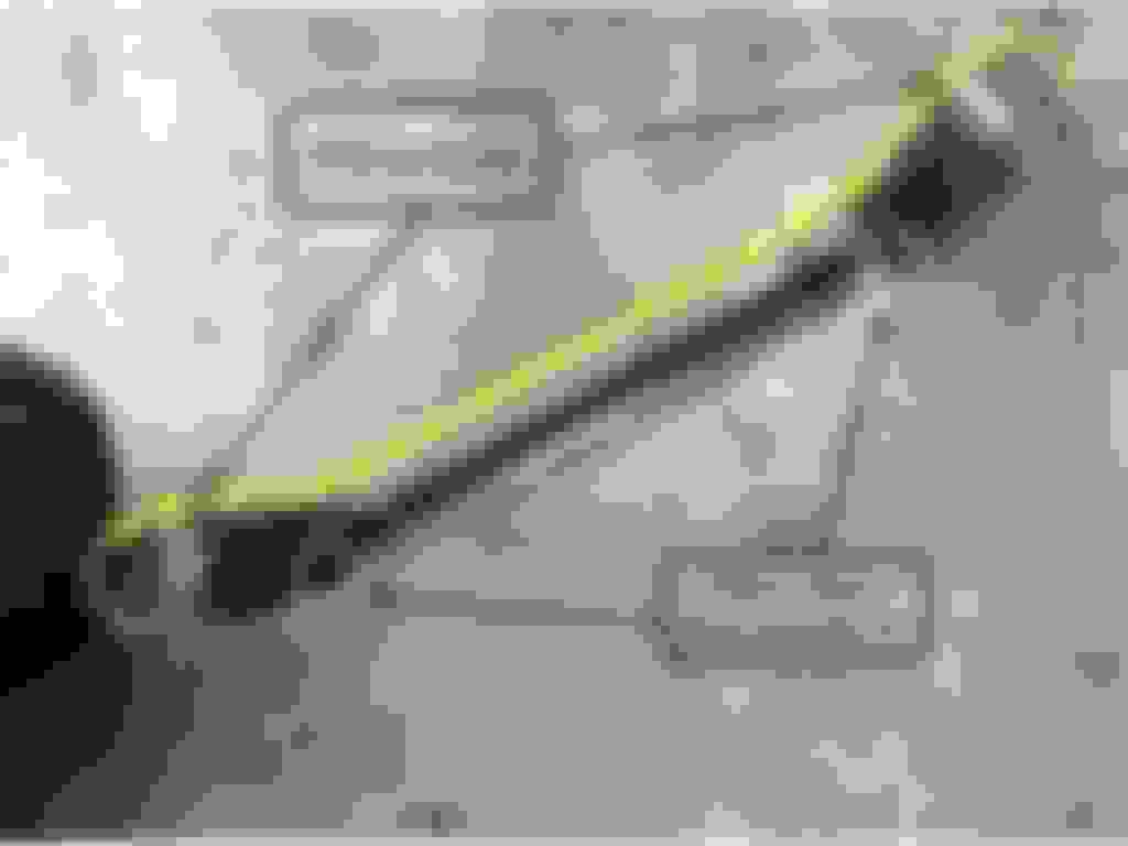
A modification has been discovered. Why is no one surprised?
This crossmember is behind the engine mount crossmember and ahead of the transmission mount crossmember. There are two bolts holding it to the top frame rail and the pivot arm bracket bolts to it below the lower frame rail.
This crossmember has been cut lengthwise reducing it�s width (see yellow line).
Here you can see where they got off course with the blade as well as bifurcating several holes along the way. When I pull the engine and trans out of my �76 F-100, I should be able to see what this crossmember is supposed to look like, what else bolted to it and so on. It�s not referenced directly in the Ford truck shop manual for this year. Perhaps someone here has better references than I.
I don�t yet understand why this was done. My initial theory that it was to accommodate the dual exhaust system doesn�t appear to hold up. There was no interference that I could see. Of course this wouldn�t be the first time that unnecessary surgery was performed.
In any case, all of these parts have been cleaned-up and painted. Tackling the engine bay itself remains on the to-do list. No doubt, more mysteries lie ahead. This is the fun of it all, right?
Engine Work: Prepping the Operating Room (organizing parts)
New parts are starting to arrive. Today, the Edelbrock top end kit (aluminum intake and heads plus cam, lifters, timing chain bolts and gaskets) arrived and the Scat full rotating assembly (crankshaft, bearings, rods, pistons and rings) are slated to arrive next week.
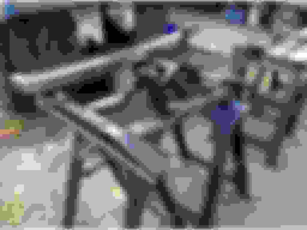
I assembled a shelf system atop a rolling platform to organize the new and reused parts. Here�s what that looks like today. The tie down straps are not due to the aluminum intake manifold and heads being lighter than air. My shelving system is very stiff along one plane and not stiff enough along the other. I�ll be needing to fabricate some braces before I can remove the tie downs.
Here�s a view of the shelf from another angle. I haven�t yet started to arrange things in terms of assembly sequences. After I get the shelf stabilized, it will become a key part of the build process.
So I started inspecting the Edelbrock top end kit that arrived yesterday. Here is one view of the heads showing the valves and the intake runners.
This view compares the intake and exhaust ports. As I understand it, these heads are a slight improvement on the medium-riser 427 heads.
I�ve added the studs and the one inch carb spacer from the cast iron unit this aluminum manifold replaces.
It�s an original ford part as can be seen here. There is a provision in this spacer for the exhaust crossover on the cast iron manifold but that crossover doesn�t exist on the Edelbrock unit. I don�t think that this vestigial tail will present any problems. Or should I get a new spacer?
Here is the manifold, spacer and 800 CFM carb. Clearly, I have a lot more mock-up work to do here as I figure out linkage (accelerator and kick-down), vacuum management, which holes to plug and so on.
It�s pretty clear that Edelbrock doesn�t want me to use E-85 so I won�t. The hope and expectation is that pump gas will be perfectly adequate.
As soon as I get the lower end kit with the .040� over pistons, the machine shop can start boring the block.
This is some great progress. Must feel really good.
Wish I was somewhere close to what you're doing right now... Been sitting "at the drawing board" for almost 3 years now trying to figure out what I want to do with my engine build...
Aaron-71,thanks for following along. It's a tightrope act between the extremes of recklessness and analysis paralysis. With more days behind me than in front of me, I tend toward rapid decision making. You'll find your way and I hope that my experience can help a little.
A modification has been discovered. Why is no one surprised?
This crossmember is behind the engine mount crossmember and ahead of the transmission mount crossmember. There are two bolts holding it to the top frame rail and the pivot arm bracket bolts to it below the lower frame rail.
This crossmember has been cut lengthwise reducing it�s width (see yellow line).
Here you can see where they got off course with the blade as well as bifurcating several holes along the way. When I pull the engine and trans out of my �76 F-100, I should be able to see what this crossmember is supposed to look like, what else bolted to it and so on. It�s not referenced directly in the Ford truck shop manual for this year. Perhaps someone here has better references than I.
I don�t yet understand why this was done. My initial theory that it was to accommodate the dual exhaust system doesn�t appear to hold up. There was no interference that I could see. Of course this wouldn�t be the first time that unnecessary surgery was performed.[/QUOTE]
I don't know exactly what it's there, but I don't have anything bolted to mine on my 76 f150. Maybe is for "protection"? I can take pictures when I get home from work if you'd like..
I don't know exactly what it's there, but I don't have anything bolted to mine on my 76 f150. Maybe is for "protection"? I can take pictures when I get home from work if you'd like..
I've since taken a look at my '76 F-100 and my '77 F-250 and they also appear to have been cut right along a line that intersects a number of holes. Maybe this was a factory mod or perhaps something commonly done at dealerships. Neither of these vehicles appear to have been altered from stock as the '76 F-150 certainly was (dual exhaust system).
The purpose of this crossmember seems to be to support the brackets that hold the pivot arm bushings in place. There is only one bolt on each side connecting each of the two pivot arm bushing brackets.
While I can appreciate the importance of supporting the pivot bushing brackets, these things also act as a scoop and a shelf for road dirt and grime. Here's my F-250:
I just looked at my tear down pics on my 79 F350 srw, The only thing that was attached to that crossmember was my brake and fuel lines on the driver side. My pics arent straight on of that crossmember but mine isn't cut at all. I know that I have that xmember in my parts room and can take a pick of it if you would like, won't be posting till tomorrow as this is a stay clean day.

 03-06-2016, 10:19 AM