
Inside of the instrument panel
#1
 04-17-2014, 07:05 PM

Join Date: May 2010
Location: Salt Lake City
Posts: 38
Likes: 0
Received 0 Likes
on
0 Posts
Inside of the instrument panel
Does anyone know of a schematics drawing of the inside of the instrument panel? Or maybe someone has some pictures of the inside?
I'm looking into an idea of integrating the tach into the existing instrument panel, but I need to know what the guts consist of..
I'm looking into an idea of integrating the tach into the existing instrument panel, but I need to know what the guts consist of..

#4
04-17-2014, 08:39 PM
Join Date: May 2010
Location: Salt Lake City
Posts: 38
Likes: 0
Received 0 Likes
on
0 Posts
I'm years out from engineering my idea, but here's what I'm thinking: integrate a second needle into the speedo and have the tach use the speedos numbers. You know, kinda like the minute and hour hands on a watch.
It's going to take a fair amount of engineering. But thankfully with 3D printing these days, I can custom build parts really cheaply.
So what I would end up doing is using an Arduino to interpret the tach cable and then have the Arduino control a servo that runs the tach needle.
So I was curious as to how hard it would be to get inside the speedo box to integrate a second needle.
Make sense?

#6
04-17-2014, 08:56 PM
Join Date: May 2010
Location: Salt Lake City
Posts: 38
Likes: 0
Received 0 Likes
on
0 Posts
Yeah... but I'm going to set my mind to it and figure it out.
Thanks for this picture, very helpful. I think this confirms a suspicion: I'm probably going to need the Arduino to read in the speedo as well.
In all honesty, I think that's going to be the hardest part is having the Arduino read in the speedo and tach. Engineering it past there *should* be easy.
Thanks for this picture, very helpful. I think this confirms a suspicion: I'm probably going to need the Arduino to read in the speedo as well.
In all honesty, I think that's going to be the hardest part is having the Arduino read in the speedo and tach. Engineering it past there *should* be easy.
#7
04-17-2014, 08:56 PM
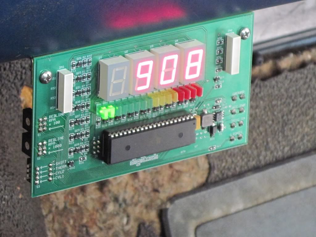
Sounds like we've got a fellow microcontroller enthusiast here, so I'll post my homemade digital tach:
https://www.ford-trucks.com/forums/1...tach-pics.html
To get you started, I'll give you a hint: you can't get engine RPM from the speedometer cable, if that's what you meant. Also, store-bought tach's don't have a cable like a speedometer would; they operate based on the signal at the coil primary winding (mine takes it to the next level).
Trending Topics
#8
04-17-2014, 09:10 PM
Join Date: May 2010
Location: Salt Lake City
Posts: 38
Likes: 0
Received 0 Likes
on
0 Posts
Sounds like we've got a fellow microcontroller enthusiast here, so I'll post my homemade digital tach:
https://www.ford-trucks.com/forums/1...tach-pics.html
https://www.ford-trucks.com/forums/1...tach-pics.html
LMAO. No, not trying to get tach from speedo. That'd be quite the feat, huh? What I meant was I think I'm going to need to have the Arduino interpret the speed from the speedo cable and the tach from the tach cable. Your post is going to get me very far!
#10
04-17-2014, 09:17 PM
Join Date: May 2010
Location: Salt Lake City
Posts: 38
Likes: 0
Received 0 Likes
on
0 Posts

#11
04-17-2014, 09:24 PM
Join Date: May 2010
Location: Salt Lake City
Posts: 38
Likes: 0
Received 0 Likes
on
0 Posts
From your other post:
Oi. I have a lot to learn.
Most tachometers are voltage based, meaning they read the voltage of the primary coil between the winding and the ignition module (or points). The problem is that the waveform at this point is subject to heavy inductive ringing, and can reach several hundred volts when the coil is fired (even though this is the lower voltage side). Instead of trying to condition this waveform, my tachometer is actually current based. The primary current is very simple and continuous due to the inductive nature of the coil's primary winding. The primary current almost resembles a sawtooth waveform.
My tachometer works by passing the primary coil current through the aperture of a Hall effect based current transducer. That's why the trigger box has connections to go inline with the factory harness. The voltage-based output of the transducer is turned into a square wave using a comparator with hysteresis. This square wave is passed directly to the microcontroller; the microcontroller uses an interrupt-based input capture pin with a timer to measure the frequency of the square wave. The frequency of this square wave is equal to the frequency of the primary current; this frequency can be converted to RPM based on some scaling factors and the number of cylinders (configurable).
My tachometer works by passing the primary coil current through the aperture of a Hall effect based current transducer. That's why the trigger box has connections to go inline with the factory harness. The voltage-based output of the transducer is turned into a square wave using a comparator with hysteresis. This square wave is passed directly to the microcontroller; the microcontroller uses an interrupt-based input capture pin with a timer to measure the frequency of the square wave. The frequency of this square wave is equal to the frequency of the primary current; this frequency can be converted to RPM based on some scaling factors and the number of cylinders (configurable).
#12
04-17-2014, 09:34 PM
I love tagging along threads
FMC....I am looking to engineer some arduino based projects. My code writing experience was long ago so I bought a how-to book to try to supplement my C++ classes from way back when. My question is how much does C++ assist you? Or should I just buy a breadboard, MC, and some RGB's and just start playing?
....it's a really big book
....it's a really big book
#13
04-17-2014, 09:58 PM
All part of the fun.
In all honesty, I'm not a huge fan of Arduino-based building blocks because my enjoyment comes from the low-level hardware design. I personally like to do everything from scratch. That being said, I do target the same Atmel AVR microcontrollers that Arduino is based upon. Arduino has a large following and they make these type projects a lot more accessible for someone wanting to get their feet wet and build something cool without getting bogged down with too many nitty-gritty details.
Most of my microcontroller work is done in C (a subset of C++). The other alternative is assembly programming which is daunting for projects of any moderate complexity. However, there's little you can do with a microcontroller without some level of C or assembly programming ability (unless the Arduino community offers some higher-level tool, which I wouldn't be familiar with). Running executable code is what they were built for, as opposed to fixed-function devices (like logic gates that aren't "programmed"). However, don't let that scare you; the internet is full of tutorials (especially within the Atmel AVR community) that are easy to grasp, probably much more so than a textbook.
Sorry if I hi-jacked this thread too much.
FMC....I am looking to engineer some arduino based projects. My code writing experience was long ago so I bought a how-to book to try to supplement my C++ classes from way back when. My question is how much does C++ assist you? Or should I just buy a breadboard, MC, and some RGB's and just start playing?
....it's a really big book
....it's a really big book
Most of my microcontroller work is done in C (a subset of C++). The other alternative is assembly programming which is daunting for projects of any moderate complexity. However, there's little you can do with a microcontroller without some level of C or assembly programming ability (unless the Arduino community offers some higher-level tool, which I wouldn't be familiar with). Running executable code is what they were built for, as opposed to fixed-function devices (like logic gates that aren't "programmed"). However, don't let that scare you; the internet is full of tutorials (especially within the Atmel AVR community) that are easy to grasp, probably much more so than a textbook.
Sorry if I hi-jacked this thread too much.
#14
04-17-2014, 10:11 PM
All part of the fun.
In all honesty, I'm not a huge fan of Arduino-based building blocks because my enjoyment comes from the low-level hardware design. I personally like to do everything from scratch. That being said, I do target the same Atmel AVR microcontrollers that Arduino is based upon. Arduino has a large following and they make these type projects a lot more accessible for someone wanting to get their feet wet and build something cool without getting bogged down with too many nitty-gritty details.
Most of my microcontroller work is done in C (a subset of C++). The other alternative is assembly programming which is daunting for projects of any moderate complexity. However, there's little you can do with a microcontroller without some level of C or assembly programming ability (unless the Arduino community offers some higher-level tool, which I wouldn't be familiar with). Running executable code is what they were built for, as opposed to fixed-function devices (like logic gates that aren't "programmed"). However, don't let that scare you; the internet is full of tutorials (especially within the Atmel AVR community) that are easy to grasp, probably much more so than a textbook.
Sorry if I hi-jacked this thread too much.
They say arduino has its own language. But with include, cin, cout and loop and such I would beg to differ. I am going to start with sequencing projects to get my feet wet. Shift registers and flip flops and the like. Ah heck, I'll just order some components and start building. See what happens
Thanks for the response.
#15
04-18-2014, 12:21 PM
Join Date: May 2010
Location: Salt Lake City
Posts: 38
Likes: 0
Received 0 Likes
on
0 Posts