
Custom Keyless Entry System For My 1994 idi
#1
 11-09-2013, 10:21 PM


Custom Keyless Entry System For My 1994 idi
For one of my classes we were asked to build some sort of device which incorporates a microprocessor. About a month ago I did not know a thing about circuits or programming but I've managed to learn the basics through this project.
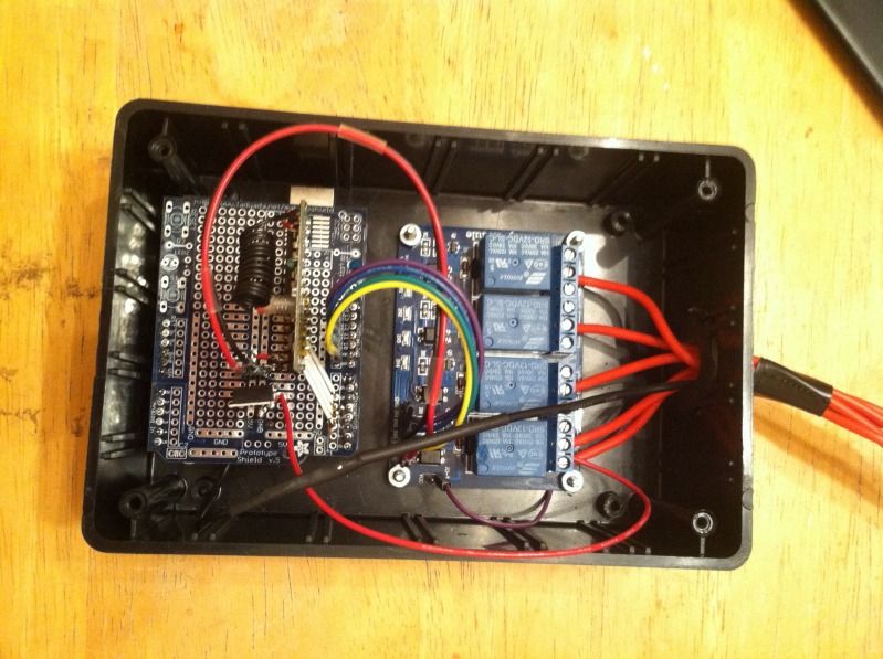
I built a "keyless entry module" using an Arduino Uno and a 12v relay board for my 1994 f250 idi turbo.
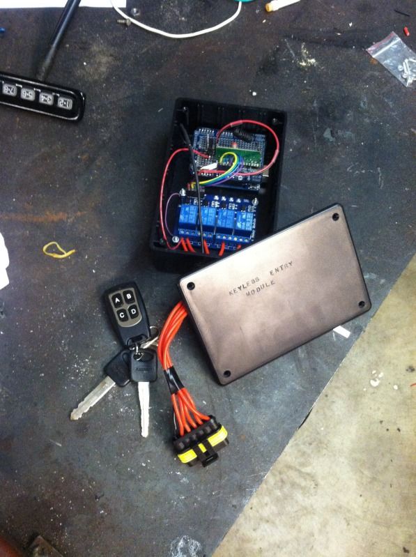
Button A locks the doors, the running lights flash to confirm that the doors have been locked. B unlocks the doors. C turns the headlights on for 10 seconds. This is very useful to me for lighting up the front door when I am looking for the house keys at night. D is currently unused.
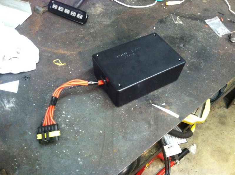
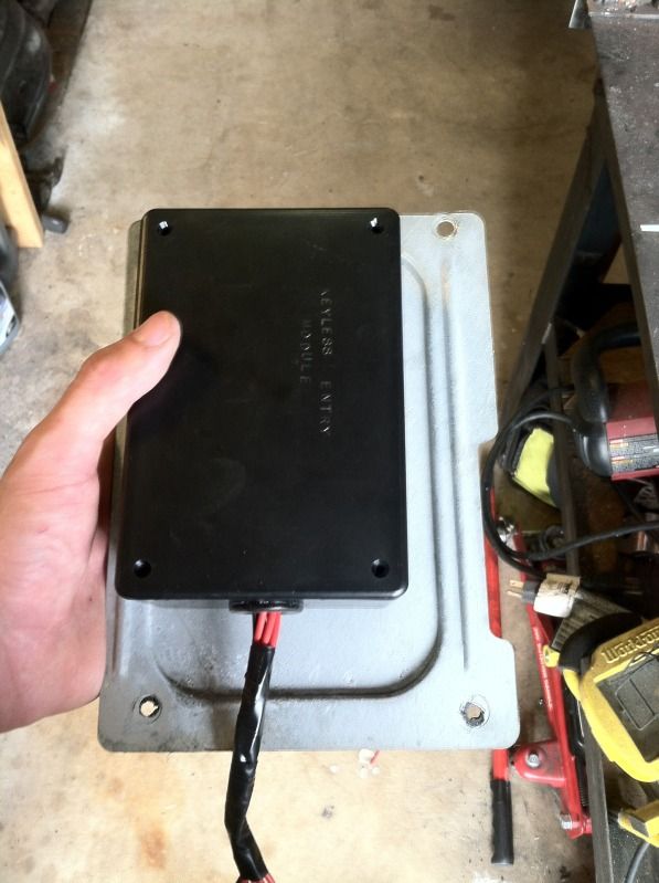
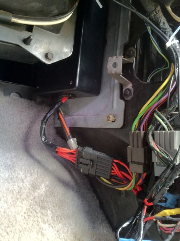
I found this plate behind the passenger kick panel. It was a great place to mount the module. I used a 6 pin weather proof plug for easy removal of the module from the truck. The module fits perfectly behind the factory trim and is completely out of sight.
In the end I could have bought an aftermarket kit or even added the factory keyless entry for a probably less money and obviously less work. But that wouldn't have made for a very good project. Plus with the Arduino I can control almost anything I want in the truck with my key fob if I decide to do more with this one day.
If anyone is interested in the code or more info on the circuit I can post that up as well
I built a "keyless entry module" using an Arduino Uno and a 12v relay board for my 1994 f250 idi turbo.

Button A locks the doors, the running lights flash to confirm that the doors have been locked. B unlocks the doors. C turns the headlights on for 10 seconds. This is very useful to me for lighting up the front door when I am looking for the house keys at night. D is currently unused.


I found this plate behind the passenger kick panel. It was a great place to mount the module. I used a 6 pin weather proof plug for easy removal of the module from the truck. The module fits perfectly behind the factory trim and is completely out of sight.

In the end I could have bought an aftermarket kit or even added the factory keyless entry for a probably less money and obviously less work. But that wouldn't have made for a very good project. Plus with the Arduino I can control almost anything I want in the truck with my key fob if I decide to do more with this one day.
If anyone is interested in the code or more info on the circuit I can post that up as well


#5
11-10-2013, 08:44 AM
I sourced most of my parts from ebay, radioshack and adafruit.com
The receiver triggers a corresponding input pin on the arduino, which it senses and then drives an output pin low, which triggers the relay to the normally open position. Each NO on the relay is connected to 12v, so when the relay closes from the button press, it sends 12v to the wire which is connected to the common of that relay.
The 4 channel relay board was sourced from an ebay seller. One relay controls the wire that gets 12v to powers the lock motor to unlock and another relay to spin the lock motor the other way, which is lock. The third relay puts the 12v to the wire which powers the running lights, and is set to trigger when the lock relay is also triggered. The fourth relay is spliced into the wire which gets 12v to power the headlights. It is on a delay of 10 seconds so that when I press the button it will stay on for that set time.
This is all powered with a voltage regulator which can take a source of up to 36v and step it down to an output of 5v, which the Arduino is powered by. The Arduino board actually has a built in regulator which is spec'd to handle I believe 18v, but I liked the insurance of a 2$ regulator in the noisy auto environment.

#7
11-10-2013, 11:23 AM
I thought about this. I would need a couple more relays. The glow plugs shouldn't be too hard. Just put a delay so they stay on for a set time just like my headlights. However, my fast idle is not currently working, and fixing that is not currently in the budget by the time this project is due.

Thread
Thread Starter
Forum
Replies
Last Post
big orange beast
1999 - 2003 7.3L Power Stroke Diesel
2
12-02-2011 06:29 AM
'02strokerpilot
1999 - 2003 7.3L Power Stroke Diesel
6
01-16-2010 07:06 PM