When you click on links to various merchants on this site and make a purchase, this can result in this site earning a commission. Affiliate programs and affiliations include, but are not limited to, the eBay Partner Network.
Voltage Drop Testing How-To: Fix That Slow Starter
Greetings All,
I wrote the following how-to guide about 15 years ago for a Jeep website I used to have. The website is no longer online (got overwhelmed with the email it generated), but I wanted to pass along this method of troubleshooting for a slow-turning starter, or any similar electrical fault.
It's called a voltage drop test. When I learned about this VERY simple test years ago, the proverbial light bulb (no pun intended) illuminated over my head, just like in the cartoons. I realized if I could put this simple test to practical use, I could be lazy and still look like a hero in the process. The version I'm presenting is a bit of a hybrid, as it also includes a battery load test. Hopefully this will help somebody down the road.
Shortly after I learned how to do this test, a friend called me in the middle of the night, in FullPanicMode™ because he couldn't fix his starter and needed the car in the morning to get to his new job. He had already tried two starters, two solenoids, and a battery. He was about to try another battery but the parts store was closed. In less than five minutes, I found a bad cable crimp that appeared perfectly fine on the outside. I looked like a genius and went home and back to bed. The only downside is that idiot friends tend to call you in the middle of the night for help...
I've searched online for a good description of the test, but almost everything I found was written for people that already had a good understanding of electrical troubleshooting. Rather than preach to the choir, this is intended for the layman. At my day job, I am electron wrangler. While I'm not allowed to wear a cowboy outfit, my employer pays me to ensure that various electrons traveled exactly where intended and nowhere else. The electrons I corral happen to be on aircraft, but the principles are the same no matter the application.
Practically every electrical textbook starts with several dreary and intricate chapters explaining why electricity behaves the way it does. Most textbooks omits one simple fact: Nobody truly understands why electricity works. We know how, i.e. the cause and effect of the whole process. But why the electrons travel to and fro is beyond normal understanding and is merely theory. Unless you like to fill your head with extraneous information, skim over the valence shells and free electrons covered so well in electrical textbooks. While no doubt true, you barely need to know any of it to understand basic electricity. Such information tends to scare off people. If you can grasp that invisible thing-a-ma-jiggies (electrons) travel predictably and can be harnessed to do useful work, you will be all set. I guess I shouldn't complain. If everybody had a good understanding of electrical troubleshooting, I'd have to get a real job.
There are only two concepts needed for a basic understanding of electricity. The first is that electricity always travels in a closed loop. Without the loop, no flow occurs. The second concept is that any circuit is already chock full of electrons, whether flowing or not. Even a scrap piece of wire sitting on your garage floor is full to the brim with electrons. If you could push on an electron, a chain reaction takes place. Imagine a tube packed tightly with marbles. Pushing on a marble at one end displaces another at the far end. My dog is the same way. When Alpo goes in one end, a chain reaction occurs and almost immediately something needs to come out the other end. A nearly identical process occurs with electricity. Fortunately, unlike my dog, it's electrons that come out the other end, and the transfer is instantaneous.
If your tube of marbles were formed into a loop, that is a crude circuit. Imagine a Hula Hoop full of marbles, with no gaps between them. If you could somehow propel one marble, all of the other marbles would be pushed along by the chain reaction. Work with me, don't ask how can you push on a single marble inside a closed loop. Pretend you have shrunk yourself small enough to fit inside, but don't come crying to me if you get crushed by the marble behind you. Try to stand to the side a little bit and please be careful. (Watch out if a kid picks up the Hula Hoop.) Your tiny self is the force supplying the pressure that move the marbles inside the Hula Hoop. In an electrical circuit, the pressure comes from the generator, battery, or both. These moving electrons can be harnessed to perform useful work such as spinning a motor, powering a light or heating Pop-Tarts.
That is an oversimplified understanding of electricity. There is much more, of course, but I'm not a professor teaching a graduate course. I'm merely trying to help you figure out why your starter spins slowly over or why your headlights are dim. These ramblings are intended to help you troubleshoot an existing circuit which is either inoperative or performing poorly. First you will test for adequate pressure behind the electrons (This is the battery load test). We'll also test the rest of the circuit for any unwanted restrictions that can cause poor performance (This portion is the voltage drop test). Not all restrictions are unwanted, but that is another bedtime story. We are only searching for unwanted ones. No math is needed nor will any component or wiring need to be disconnected. That last bit is so important, I will repeat it. No components or wiring needs to be disconnected. Put your wrenches away for this troubleshooting. You only need a voltmeter.
A teensy bit of Voltmeter 101 is in order. Notice I said voltmeter, not ohmmeter. Checking wiring with an ohmmeter is time consuming. Connections must be undone, and the results are inconclusive even if perfect continuity is indicated. More on that later. Back to our voltmeter. A voltmeter measures the pressure difference between the two leads. That's it. Nothing more, nothing less. If connected across the battery terminals, the pressure differential (voltage) is displayed. Here is a very basic example of a voltmeter hookup, reading the pressure present on a 12 volt battery:
Reading battery voltage, ho hum... Note the sheet metal screws on the battery posts.
"Okay, you're boring me. I know how to read battery voltage." Remember, the voltmeter is only reading the pressure differential between the two leads. What happens if you connect the two leads to each other instead? There is no pressure difference, and thus no voltage indicated:
Meter leads touching: 0.000 volts
You may suddenly find yourself consumed with the urge to hurt me. Your starter barely turns, and I'm delving into the seemingly unimportant details of a voltmeter. Before proceeding (I'm talking about reading further, not hurting me) it is vitally important to understand that there is no pressure difference between the meter leads when they are connected, and thus 0.000 volts is displayed. That sounds pretty basic, but what does that have to do with anything?
If I haven't lost you yet, consider this next step. Instead of the meter leads connected directly to each other, what would happen if they were joined by a "Perfect" conductor? (There is no such thing as a "Perfect" conductor, but "Pretty Darn Good" is well within our grasp.) With the meter leads joined by a "Perfect" conductor, it is the same as if the leads were directly connected:
Meter leads connected by "perfect" conductor: 0.000 volts
That stray piece of wire shown above happened to be completely isolated from anything else but the meter. Consider if that "Perfect" conductor was part of a circuit in motion. Even if bazillions of electrons were zipping past (very high pressure or voltage) there would be no pressure differential between the meter leads. This is the very crux of this simple troubleshooting technique. This allows us to verify that any circuit element is allowing electrons through without any unwanted resistance. In this TooMuchFreeTimeVision™ image, the happy blue electrons are zipping past as part of a completed circuit. As with the piece of wire shown above, the meter is indicating 0.000 VDC:
Now let's place a restriction in the previously "Perfect" conductor. For the moment, consider it an unwanted restriction like a loose crimp or multiple broken strands. The restriction may not be as abrupt but is enough to cause a difference in pressure along the conductor. If too many electrons try to pass through, they will bunch up on the upstream side of the restriction. Remember this conductor is part of a circuit in motion, with the electrons traveling in a loop and performing useful work, such as powering a light. Notice how the meter is not reading zero any more:
The voltage displayed is directly proportional to the amount of the restriction. Pretty cool, huh? With a simple meter hookup, a circuit under load can be easily tested for any unwanted restriction, or voltage drop. This is called a voltage drop test and is amazingly simple in use. It can be a bit difficult to grasp initially, so reread this section until it makes sense. Then sit on your hands, because you'll want to slap yourself once you realize how simple it is. The closer the voltage reading is to zero, the better the conductor is. Don't forget the all-important fact that this only works on a circuit in motion.
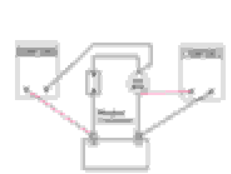
Here is an example of a light bulb with a power source and switch, utilizing "perfect" conductors. The first step is to verify adequate voltage across the two battery posts when under load. As long as the power source is supplying the proper voltage, the bulb shines at the specified brightness. The meter on the left is checking the entire positive leg of the circuit, including the switch. The meter on the right is checking the entire negative leg of the circuit. Note how the meter leads are directly on the battery posts so that any faults in the cable terminals will be measured. (A small, self-tapping screw driven partway into a battery post makes a handy place to clip a meter lead.) Although two meters are shown for illustration purposes, only one is needed:
Bulb shining at full brightness
Now our simple circuit has a fault causing the bulb to shine dimly. With the same meter hookups under load, the trouble is quickly isolated to somewhere between the negative battery post and the negative terminal on the light bulb:
Bulb shining dimly
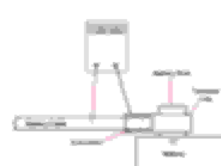
The problem can be narrowed down even further. The faulty wire can be electrically separated in two parts by poking one meter lead through the insulation near the middle. (Seal the hole with super glue afterwards.) Check for voltage drop between the middle of the wire and each end. After determining which end is at fault, further isolate the fault by moving the lead directly to the terminal lug instead of the battery post. Corrosion inside the crimp has caused the problem in this case. Instead of trying a new battery, switch or bulb, the offending cable is quickly identified and replaced with no wasted time or money:
Voltage drop across corroded connection
Various sources give different values for maximum voltage drop. I would recommend no more than 0.500 volts total on either the positive or negative leg of any circuit. Remember, the closer to zero the better, so 0.200 volts is a better limit. Disregard any readings you get when the circuit is not under load, as you can read system voltage in some instances.
Despite this convincing demonstration, you're still saying to yourself, "No thanks, I prefer to spend hours troubleshooting inconclusively with an ohmmeter. I'll spend my time disassembling everything to check continuity. I'll scrub every connection with a wire brush, and maybe even draw blood a few times from the sharp bristles. I like to waste valuable time and perform way more work than is necessary. Maybe I can even throw away my hard-earned money by replacing some perfectly good parts." Granted, in the example above, you'd have eventually found the problem by checking resistance.
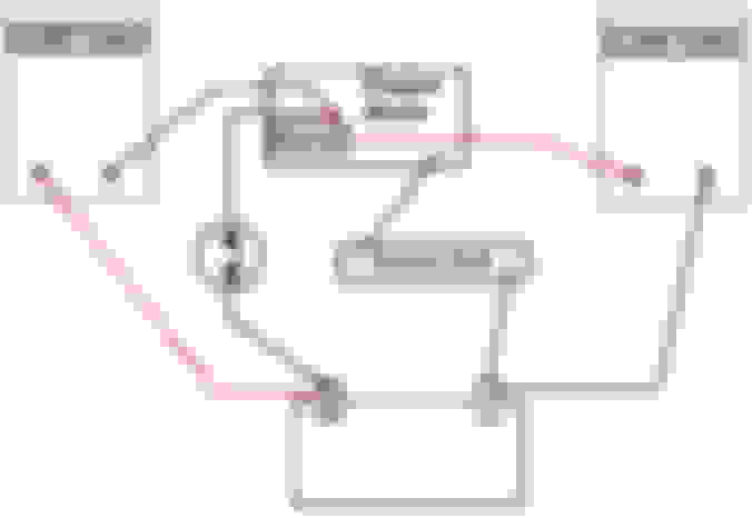
Let's look at another possible situation with a poor connection. Ordinary voltage and resistance checks will steer you down the wrong path. Shown is a frayed wire, where at least one strand is still providing continuity. However, not enough current can flow through the frayed section for the circuit to work properly. A loose or corroded crimp, where at least one strand is making good contact, may also behave in the same manner. In this example, the bulb is either dim or not illuminated at all. "Forget this mumbo-jumbo voltage drop testing, I'll just check for voltage at the bulb socket," you say to yourself. With the bulb removed and the circuit not under load, you will get VERY misleading results. The voltmeter draws so little current that enough electrons can easily pass through the remaining single strand. "Hmm," you say, "Plenty of voltage, so the switch and wiring must be good."
A misleading voltage reading at the empty bulb socket
Hopefully you'll get suspicious after the 5th or 6th light bulb. Reinstall the bulb so the circuit is under load and run the amazingly simple voltage drop test. In this example, the frayed section is impeding the current flow so that inadequate voltage is available at the bulb. The voltage drop test on the ground leg is showing 4 volts, when ideally it should be as close to 0.000 as practical. The bulb was only seeing 8 volts under load, even though 12 volts erroneously appeared to be available by checking voltage at the socket:
Found the fault with a voltage drop test.
The voltage drop test has incredible advantages over testing resistance with an ohmmeter. In the example above, a test with an ohmmeter would have showed good continuity yet the damaged wire was incapable of carrying the needed current. A similar situation would occur with a wire that is too small to conduct the needed flow of electrons. Such an undersized wire would show perfect continuity with an ohmmeter, yet become a restriction in a circuit with heavy current. Due to the inconclusive results and the need to disconnect the components, I consider troubleshooting with an ohmmeter a potentially misleading waste of time. Ohmmeters do have their place, like testing a fuel gauge sender but for most troubleshooting the voltage drop test is the way to go.
Undersized replacement cables are a big problem. (It's even worse for 6 volt starter systems, if you have an antique car.) Some cable manufacturers save on cost by using a marginally sized conductor and adding a thick layer of insulation, giving the impression of a much beefier cable. Yet when you try your starter, the conductor is incapable of delivering the massive current flow required. In a common troubleshooting mistake, the cables are assumed (Danger! Danger!) to be good since they are brand new. Then after replacing the battery, starter, and starter relay, you are still scratching your head and hoping your wife doesn't find out how much money you've wasted. What gives?
Well, now it's time to put our new knowledge into use. The exact same voltage drop test is used to troubleshoot a slow-turning starter. The initial step requires verifying adequate battery voltage under the load of the starter. The battery must be fully charged. Verify the charge with a specific gravity tester if there is any doubt. Pull and ground the center lead from the distributor so the engine won't start. Crank the engine for 15 seconds. For a 12 volt system, battery voltage should not drop below 10.0 volts. Some sources say 9.5 is acceptable, but I prefer the higher value. (On a 6 volt system, battery voltage should not drop below 5.00, or 4.75 volts depending on the source.) Remember to take the readings directly on the battery posts to eliminate any problems with the cable connections. I highly recommend driving a sheet metal screw into each battery post as a place to connect the test leads.
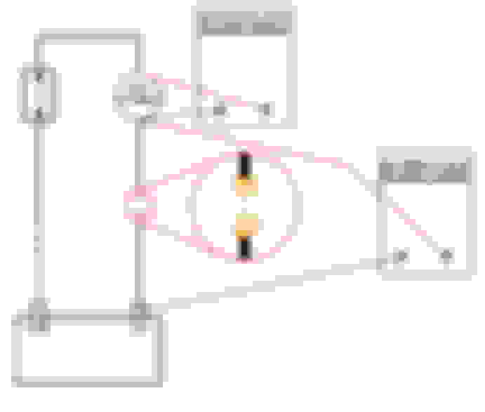
If the battery voltage is adequate under load, proceed with the voltage drop test on the positive and negative legs of the circuit. Similar to the light bulb circuit shown above, here is a diagram of a typical starter circuit. This image shows a system in good order with zero voltage drop on both legs of the circuit:
Note the meter's (+) lead on the starter housing
Note the tricky ground path for the starter. Current must flow through the starter mount bolts to the engine block, then via a jumper to the frame, and then via a second jumper to the battery. A problem at or between any of these components can cause slow cranking. By performing a voltage drop test between the starter case and the (-) battery post, any problem in the ground circuit can be quickly isolated. On the positive leg, the meter is connected between the (+) battery post and the insulated terminal on the starter. Make the initial connection directly on the insulated terminal, not the nut or cable end. Otherwise, a problem between the cable end and the starter terminal would not be apparent.
With caution for the moving fan blade and belt, wiggle the cables while testing under load. This will aggravate any marginal connections. Growing a third hand or using a helper may be required. This may help you find an intermittent problem.
Isolate and correct any problems found in both circuit legs. The only time a problem would be indicated with the starter itself is if battery voltage is adequate while cranking and both circuit legs showed near-zero voltage drop. In that case, either the starter needs repair or the engine is binding internally, causing slow cranking.
If you find the starter spins the engine adequately with the ignition disabled, but slows down once the ignition is reconnected, your ignition timing may have too much advance. Try retarding the timing a few degrees and see if that helps. (Thanks Dave!) Edit: In a related discussion in another thread, I prodded Dave for more details and he graciously complied:
"It's just like you would think if the piston was coming up, fired early, and was trying to be pushed back down in bore. The engine turns over and then almost stops when a cylinder fires, and it turns over again till the next cylinder fires and it almost stops. It does this 4 times per revolution on a v8. No mechanical noises or anything like that, the starter sounds normal but it can never build up any speed because it keeps getting almost stopped."
Note the important observation of the starter almost stopping and then speeding back up again until the next cylinder fires. This pronounced variation in starter speed is a big clue when troubleshooting a slow starter.
When troubleshooting a starter circuit, more advantages of voltage drop testing becomes apparent. With an electrically activated switch like a starter relay, the main contacts are only closed when the coil is energized. Yet the power must be off for a resistance check, ruling out the use of an ohmmeter. A voltage drop test across the terminals will easily check the current carrying capability of the contacts. Another advantage involves the ability to find the seemingly insignificant amounts of resistance that can slow down a starter. As an example, with a 12 volt starter drawing 150 amps, a cable run with a mere 0.040 ohms resistance will drop available voltage in half at the starter. It would be difficult to find 0.040 ohms with an ohmmeter. All but the most expensive ohmmeters could not accurately read that amount. The integrity of the test lead connections could easily induce far bigger errors. However, a voltage drop test will quickly pinpoint the problem.
If you do find a voltage drop problem, after making repairs, measure the voltage at the battery under load again. Since you have now corrected an unwanted restriction that was slowing the flow of electrons, it's possible a marginal battery can't handle this increased (actually normal) demand. A restriction in a cable could have been masking a problem with the battery itself. You would have fixed one problem, but it's important to retest the battery under load in case there was a second problem, hidden by the first.
One word of caution is in order when troubleshooting a slow turning starter. Battery cables that can't carry enough current, whether from damage or inadequate size, will get hot. After repeated cranking attempts, you could burn your hand so please use caution. This is also a quick and dirty troubleshooting technique. Run your hand carefully along the cables and feel for any warm areas, especially at the crimps for the cable ends. If a cable gets hot, there is a restriction inside.
One last suggestion on this amazingly simple test, if I may. I highly recommend using a digital voltmeter, autoranging if available. This test can be done just as well with an analog (needle movement) meter, but greater caution is required. An analog meter will be damaged by reverse polarity, with the needle trying to drive below zero. A digital meter merely shows a (+) or (-) depending on the polarity. While an analog meter can accurately read the minute voltage values encountered, you must manually select the range. Then if the circuit is unloaded, the needle can travel beyond the high range of the scale, also causing damage. A digital meter won't be damaged if the value exceeds the range of the scale. An autoranging digital meter is even better, as the most accurate range is automatically selected for whatever value is present. An autorecord Min/Max function is even better, as you can then do all this testing without a helper. To get my trusty Fluke 83 meter away from me, you would have to pry it from my cold, dead hands, but even a $10 cheapie digital unit would perform satisfactorily.
More info about testing voltage drops can be found in the automotive section of the Fluke Meter web site. While excellent details are provided, it only shows individual components and connections being tested within a circuit. For initial testing, check the entire length of each circuit leg. If that passes, there is no need to measure the voltage drop within segments of that circuit leg.
To recap, here's how to run the test for a slow-turning starter. This complete process will only take several minutes and can save you LOTS of grief:
1) Disable the ignition. (Disconnect and ground the center lead at the distributor, for example.)
2) Drive a small sheet metal screw into each battery post, as a place to connect your voltmeter test leads.
3) Connect your voltmeter (+) lead to the battery (+) post. Connect the (-) lead to the (-) post.
4) Engage the starter for 15 seconds. Make sure the battery voltage does not drop below 10.0 volts under load. This portion of the test is checking the condition of the battery. A low reading here indicates a weak charge or battery on its last legs. Recharge or replace the battery and run this step again.
5) Keep the ignition disabled. Keep the voltmeter (+) lead on the battery (+) post. Move the (-) lead to the big electrical stud on the starter. Don't connect to the cable end, but right on the stud if at all possible. This set-up will test the entire positive side of the starter circuit, including the big contacts of the starter relay, making sure current from the battery will be delivered without undue restriction. Engage the starter again. 5 seconds is adequate here. If the voltage reading is less than 0.500, the entire positive side of the starter circuit is good. Remember, the closer to 0.000 the better.
6) Keep the ignition disabled. Move the voltmeter (+) lead to the starter case. (That is not a typo, put the meter's positive lead on the starter housing.) Move the voltmeter's (-) lead to the battery (-) post. This set-up will test the entire negative side of the starter circuit, making sure the return portion of the electrical circuit is being completed without undue restriction. Engage the starter again for 5 seconds. If the voltage reading is less than 0.500, the entire negative side of the starter circuit is good.
7) If you find a fault in steps 5 or 6 (either voltage drop reading above 0.500), repair the problem and run steps 4, 5, and 6 again. Remember, removing an unwanted restriction at any point in the starter circuit will increase the flow of electrons throughout the entire circuit. Repeat step 4 to make sure the battery is still keeping up the pressure under load. Repeat steps 5 and 6 to make sure the cables are still properly handling this increased (normal) flow.
8) If steps 4, 5, and 6 test good, you've got a bad starter or internal binding in the engine dragging down the cranking speed.
9) Reconnect the ignition and add a nice comment to this thread saying how this simple test saved you lots of time and money, and what a credit to humanity I am...
The same voltage drop troubleshooting principles can be used on any electrical circuit, not just a starter in the above example. Remember it only works on a circuit that is complete and under load. And then turn off your phone at night so you don't get any desperate midnight calls for help.
Edit: I'd like to stress the importance of having the battery FULLY charged for this test. If tested with a partially discharged battery, you will get misleading results. I won't mention any names because I don't want to embarrass forum member CrucialProspect, but he did ask me to edit the test to make it more idiot-proof.
How to define a fully charged battery? There are many ways, but I've always been partial to the cheap automatic charger I've been using for over twenty years. I select the highest charging rate (10 amps in this case), hook it up, and forget it. When the little green light comes on, the battery state of charge has always been adequate for any test I've run.
There are other ways to test the state of charge. You can measure voltage and compare it to a special chart, but it's very easy to be misled if you don't carefully bleed off any surface charge. You can also use a hydrometer in each cell, but I honestly can't remember the last time I used one. The little green light on an automatic charger has always been all I've needed, and that's what I recommend.
One last suggestion about chargers: Make sure to use a full-fledged charger with at least a 10 amp charging rate, not a "battery maintainer" or "trickle charger". Those are great for keeping a battery topped off while in storage, but not for making sure a battery is properly charged for testing. In the illustrious words of forum member Tedster9, their charging rate is nothing more than a butterfly fart. Spring for a proper automatic charger and wait for the little green light for the most accurate test results. If you do need to replace your battery, remember most batteries are not fully charged in the store, so you hook up your charger overnight to be sure.
And then if your starter speed is back to normal with a fully charged battery, you'd know the problem lies elsewhere. You're probably looking at a charging system problem that's keeping the battery from getting a full charge, or a drain that's partially depleting the battery overnight.
Last edited by kr98664; 04-03-2020 at 10:24 AM.
Reason: Added troubleshooting details for too much ignition advance
Nice! The takeaway is that practically speaking, high current carrying circuits and cables and such can't really be tested for ohms, the amount of resistance that will cause serious trouble is so low it is often smaller than the +/- accuracy of the instrument itself.
Plus how does the technician know what it was before? So high current circuits are always tested for voltage drop while under load.
"It doesn't take much of an increase in resistance to cause trouble. Let's say a 120 amp alternator operates in a circuit that has a normal resistance of 0.11 ohms. If that resistance were increased to 0.17 ohms because of a bad wiring connection, the alternator's maximum output would be limited to 80 amps. In other words, an increase of only 0.06 ohms (almost nothing!) would reduce the alternator's maximum output by almost a third! Under light load, the drop in charging output might not even be noticeable. But in a high load situation, the alternator wouldn't be able to keep up."
There is one thing I would add, possibly as a caution and maybe a troubleshooting aid if you are careful and that is when looking for voltage drops, particularly in a high current circuit like a starter, poor connections can get very hot in a live circuit. Hot enough to smoke and that can be a visual clue. It also can cause burns should you happen to place your fingers on the poor connection and possibly fire if there are flammable materials present.
Nice job explaining voltage drop test. Its something i can use on my sons truck. 1984 F250 4x4. I thought it was going to be to long, but you did a good job keeping me reading further.
Excellent thread. I will feel much more confident testing electrical circuits using the voltage drop method!
I wish I would have had this thread 8 years ago when I first started my initial build. Would have saved hours and hours of trying to figure out how to use a multi-meter on the Ohm/resistance functions!!!!!!!
All I can say is �WOW�. Wish I knew this years ago in my Jeepin� days. With a wife, 5 kids all in old used vehicles I�m sure I could have saved tons of money, time and made fewer mechanics rich. Thanks !!
That's a real nice write-up, and voltage drop test works for everything electrical. Ohms testing just isn't useful for circuits carrying low voltage high current especially, a lot of people can't grok that. They have to be tested while energized, under load, for voltage drop. The resistance can be inferred that way.
Alternator/generator charging circuits are also crippled by even very low levels of resistance, often due to invisible corrosion at grounds or connections. By the time visible rust or corrosion is actually visible, the connection has likely failed altogether. Good cables and grounds are just as important or more than simply bolting on a new high output alternator. Might as well get what you already paid for.
Sometimes just unbolting or cracking open an old ground or connection and reinstalling is enough to make the electrons happy again, but it's better to take the time and clean things up with a wire brush or grinding wheel and then coat the connection with vaseline or dielectric to keep things that way. The best answers in troubleshooting threads are always something like "I checked the cables, they look OK." X-Ray vision, I guess.
The only thing I'd point out is engine starters have a duty cycle that is a lot less than one might think. 10 seconds on the starter requires 1/2 hour rest is the typical OEM figure I found. Nobody follows this, but if the cables are getting hot, what do you think is happening to the windings inside the starter? The insulation is burning off, that's what. Starters are heavy, expensive and generally a PITA to swap out so I try to baby them and not burn them up. Find something else to do in between the torture rounds on the battery, starter relay, and starter itself. Charging the battery back up, for example.
Great write-up. This is a test every mechanic needs to know how to do, shadetree and professional. I am an auto mechanic myself and you would not believe how many auto "technicians" I have worked with who did not know how to do a voltage drop test but would want to use an ohms test instead. Of course some of that falls back to poor training. One thing I would add is that a fully charged 12 volt battery will show 12.6 volts on a volt meter. The one in your pics shows 12.44 which is not a fully charged battery but probably would still work to find excessive voltage drop.
my father used to work for fluke and was part of the team that developed the digital test meter. he has his original packed away somewhere wher nobody can mess with it. the problem i am having is my starter doesn't work at all even after i jump the solenoid. so i am going to try to apply power directly to the starter.
 06-19-2016, 05:02 PM