2014 F250 Lariat Subwoofer Upgrade
#16
 03-02-2015, 04:17 PM

The problem with the factory sub signal
I transfered my sub and amp from my 7.3, and was disappointed with the 'experience' in the 2014. Same exact equipment, why?
The answer is in the filtering of the subwoofer signal. The resulting signal was 'tuned' for the factory amp and speaker(s), and is likely done with a DSP in the main entertainment computer.
OK, what does it (filtering) look like? Unfortunately, it is a single peak at 40hz, that rolls off at -12db/decade on both sides. It's filtered below 40hz to protect the factory sub, as the OEM 8" driver is operating below it's resonance frequency. Its filtered above 40hz to blend in with the main (door) speakers.
So how do you know this?? I measured the response of the system with a signal generator (cell phone w/ app) and an oscilloscope. Recorded signal level every 10hz and drew a line through the points.
So this is why some music beats the sub to death and other music has basically no bass at all. Rap or any music with significant energy around 40hz results in distortion, as the amp gain was set as a compromise to other music.
What can be done to improve the system?
The band-aid: Add a subwoofer level control as shown in post #5
Option A: Use a 'system integration' device ($$$) to sum signals and recreate the signal and EQ the bottom 40hz (if you sub 'system' -3db point is below 40hz, which it likely isn't, even if driver free air resonance is 25hz...) Audio control DQ-61, RF 3sixty....
Option B: make a analog circuit, mix sub signal and door signal to recover missing information above 40hz. Use filter in sub amp to roll it back off where you want, around 100-150hz.
So my plan is to go from band-aid to Option B. Need to plot the response of the door speakers, and depending on what it is make a simple summing circuit with 2 resistors. The levels of the signals will be different and the values of the resistors can be sized appropriately. Will keep the level **** as well.

#18
03-02-2015, 04:54 PM
Yes it's possible to add a 2nd 'head unit' just for audio, and connect to all aftermarket amps/speakers, but then you lose hand-free and voice commands, ect. It would also be possible to use the output of the factory system (speaker level, attenuated) as an input to the 2nd head unit, say with it's 3.5mm input.
Option 4 is to just connect a source (cell phone, ipod..) to the aftermarket amps directly, either with bluetooth or analog. Again the factory system could be a additional 'source' and retain audio functions (hands free, voice commands).
I built an option 4 for my 04 Cobra, but ended up '$tage 5' as defined previously.
Kilowatt Cobra Stereo Install
#20
03-04-2015, 03:01 PM
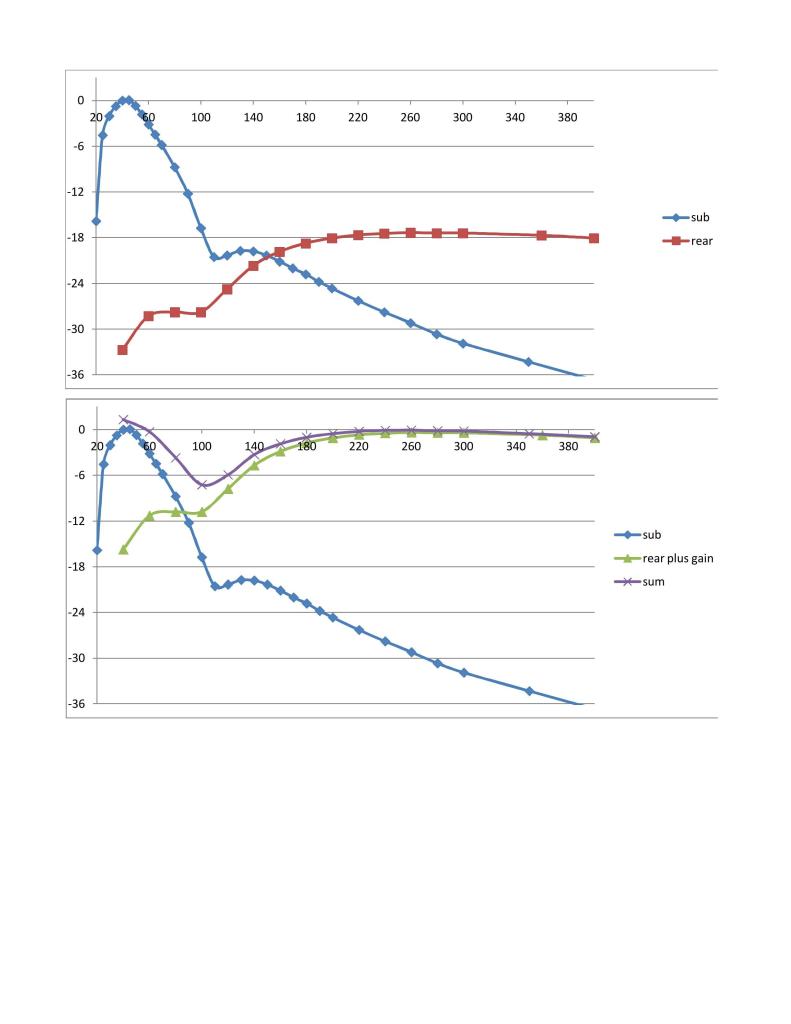
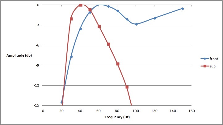
Here is what the signals look like. Instead of an oscilloscope, I use a 'true RMS' voltmeter. If the subwoofer signal is attenuated down 20db (1/10th) and added to rear speaker signal, the purple line response can be achieved, which is a definite improvement.
Next step is to build a attenuator/mixer and measure the result to see if it meets the predictions.
Next step is to build a attenuator/mixer and measure the result to see if it meets the predictions.

#21
05-04-2015, 05:44 PM
incoherent ramblings
Still in progress with this project. I have built a few circuits and continue to modify as needed. To further compound the problems I bought a different sub... which needed a different amp.. so lots of changes.
I started with a simple attenuator circuit to lower the sub output to match the level of the rear speaker. This worked fine, mixed the signals and the sound quality was MUCH improved. Bass & drums have impact and texture now that it has the rest of the frequency response, instead of boomy muddy due to overwelming energy at 40hz.
But the overall level was too low even with amp gain maxed out. So an active circuit is needed to provide some more gain. Or a speaker capable of more SPL??
Somehow against good judgment I bough a JL10TW3 last day they were on sale. Knowing hole size is not the same as ever other 10" sub, I pulled the box and enlarged hole from 9-1/8" to 9-5/8". Speaker face is taller so wasn't going to fit behind seat. Removed and modified back seat for clearance. Wired each coil to 500W and manually set gains to within 1%..... makes crackle sounds at medium SPL. Tried wiring in series, parellel, couple different amps, Rockford isn't going to work. Crap. Gain still not enough, no surprise. Need an amp matched to dual 4 ohm coil sub (RF sub had dual 2 ohm coils).
So I built another mixer (aka line converter). Instead of lowering sub signal, this one adds gain to the rear speaker signal, then mixes the two. It also filters out all frequencies outside of what I want, and adds a variable gain final output stage. Bench tested OK so I installed in truck.
Bought an Alpine 500W mono amp to replace huge 4 channel Rockford amp. Alpine class D is much more efficient and half the size. System bumps but not enough to justify the $$ over the other equipment (which was 're-purposed'). Didn't sound like mixing was working so I took a bunch of measurement and analyzed data. Somethings not right with rear channel gain. Need time and better equipment to figure it out.
Now most people would be very happy with where it's at now. It's painfully loud and will give a good headache, but the quality has some room for improvement. Some people spend free time on fantasy football, I work on my truck. I'm almost there and will post the recipe when its done.
#22
05-07-2015, 11:43 AM
more characterization of the sony system
I went ahead and characterized the rest of the system signals. Found some 2013 wiring diagrams here:
BBB Industries - TSB's & Wiring Diagrams
So this is the input, plug on the passenger side. There is only ONE stereo signal going into the 'DSP', so all the filtering and level control (balance, fader, and probably EQ) is done in the unit behind the seat. So I measured the frequency response and it flat, perfect right? Well no because it is before any volume control, ie, always the same level regardless of volume **** position.
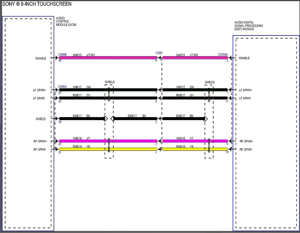
So next step was to measure the front speaker frequency response. Note that the midbass and tweeter are on their own amp channels. This is a very good thing as the filtering is done pre-amp. I found the wires in the center plug (which is numbered) according to the schematic. I measured from 500hz and down, it's -3db (0.707x) point is 38Hz. It is not 'flat' like the input signal, as it is connected to the speaker which has inductance. The frequency range we want is also at the resonant frequency of the driver so there is a slight peak (1-2db) around 80hz. Bottom line is that this signal will work just fine.


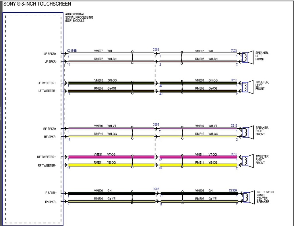
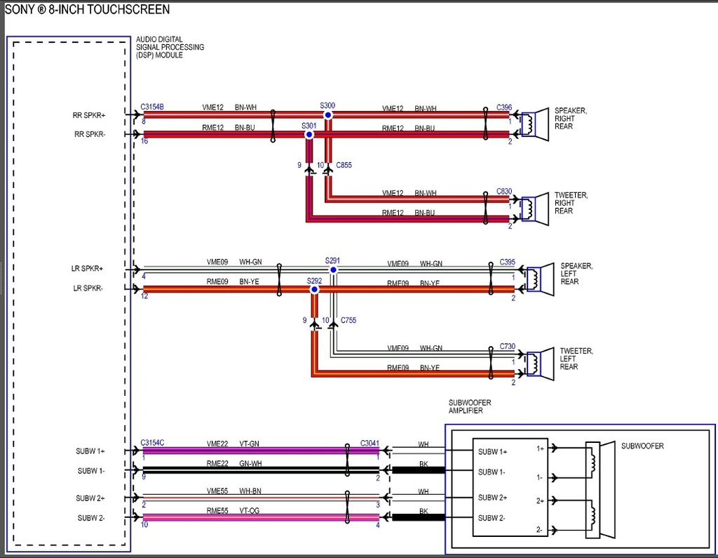
Here is the schematic of the rear speakers and sub. note the dual voice coil, and that the rear tweeters do not have a discrete amp channels.
BBB Industries - TSB's & Wiring Diagrams
So this is the input, plug on the passenger side. There is only ONE stereo signal going into the 'DSP', so all the filtering and level control (balance, fader, and probably EQ) is done in the unit behind the seat. So I measured the frequency response and it flat, perfect right? Well no because it is before any volume control, ie, always the same level regardless of volume **** position.

So next step was to measure the front speaker frequency response. Note that the midbass and tweeter are on their own amp channels. This is a very good thing as the filtering is done pre-amp. I found the wires in the center plug (which is numbered) according to the schematic. I measured from 500hz and down, it's -3db (0.707x) point is 38Hz. It is not 'flat' like the input signal, as it is connected to the speaker which has inductance. The frequency range we want is also at the resonant frequency of the driver so there is a slight peak (1-2db) around 80hz. Bottom line is that this signal will work just fine.

Here is the schematic of the rear speakers and sub. note the dual voice coil, and that the rear tweeters do not have a discrete amp channels.

#23
05-07-2015, 11:59 AM
So how does it sound? As expected, has the upper punch that was missing from the 'sub' signal. The low pass filter frequency adjustment on the amp now actually does something and can be set to achieve the desired cutoff.
Front speaker signals are at a decent level and gain on Alpine amp is about 1/2 the range. I was able to use the high level inputs on the amp directly, which is one reason I chose it.
Still want remote level control. The Alpine MRV-M500 has a jack for such a ****, however reading some reviews on amazon it appears that the **** can only attenuate the bass EQ setting (adjustable level 40hz 'hump'). So turned all the way up would result back to something similar to the 'sub' signal from the Sony system that I don't want. I want to boost or cut the whole bass range. There are several ways to achieve this.
So lesson learned here is to find and use the information available as apposed to just brute force engineering what you already know/have. Could I have got the mixer working and been happy with the result? Yes, but it add complexity and has a turn on/off thump that would have to be dealt with.
#24
05-07-2015, 01:28 PM
Awesome stuff man. Thanks for doing the leg work on this. Where(physically) did you tap into the front speaker output to provide the amp high level input? I'm assuming you did all of this behind the rear seat to minimize the work involved with running wires. Did you or do you recommend splicing with solder or another method?
#25
05-07-2015, 03:05 PM
Awesome stuff man. Thanks for doing the leg work on this. Where(physically) did you tap into the front speaker output to provide the amp high level input? I'm assuming you did all of this behind the rear seat to minimize the work involved with running wires. Did you or do you recommend splicing with solder or another method?
Yes I tapped into the wires at the amp/connector. The 'best' method would be to solder. here's how I would recommend:
1. remove the pins out of the connector. (have to find the release tab)
2. strip a 1/4" long piece of insulation off all the way around the wire about 2" from the pin. You will need to use a knife as this is not on the end of the wire.
3. wrap the splice wire around the bare copper and solder.
4. cover with heatshrink
5. re-install pins where they were
Option B is to just use electrical tape instead of heatshrink, so you don't have to remove the pins from the connector.
Option C is to cut the factory wire and splice the 3 pieces and use shrink. don't have to remove pins this way either.
Option Z is to use the correct size (red) 3M brand insulation displacement taps and male 0.25" quick connect solderless terminals. Fine for someone else's truck...https://www.parts-express.com/3m-(22...5-pcs--082-140
#26
05-07-2015, 04:33 PM
This is awesome Justin...had a feeling that the front signal was a better option. Thank you for taking the time (and for having the ability) to confirm...and for sharing.
This is one of those nuanced mysteries that rarely get solved. Since we didn't design or create the system, backing into solutions can be tricky at best and nigh impossible at worst. Very odd that Ford wouldn't signal and power the fronts and rears equally on unique channels, then tune accordingly...what's your theory on why the engineers did it this way...?
This is one of those nuanced mysteries that rarely get solved. Since we didn't design or create the system, backing into solutions can be tricky at best and nigh impossible at worst. Very odd that Ford wouldn't signal and power the fronts and rears equally on unique channels, then tune accordingly...what's your theory on why the engineers did it this way...?
#27
05-07-2015, 05:59 PM
Front speaker signal response plot
Here's the plot of the front signal. The scale is different than the others, but basically it's 'flat' to 40hz (within 3db). Most people can't perceive a 3db difference.
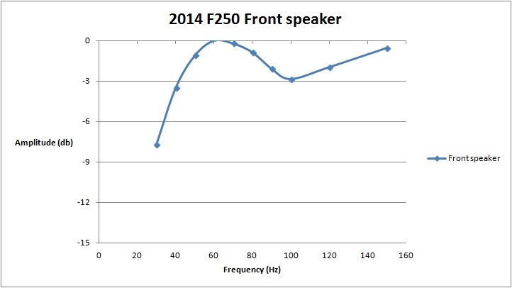
Note that doubling amplifier power results in only a +3db of SPL (loudness). If you just spent a bunch of $ on a bigger amp you will claim to notice.
here are the sub and front (normalized). Most sub systems (sub AND BOX) have a -3db point around 35-40 hz (mine included) so the difference on the low end isn't substantial.

#28
05-07-2015, 06:26 PM
This is awesome Justin...had a feeling that the front signal was a better option. Thank you for taking the time (and for having the ability) to confirm...and for sharing.
This is one of those nuanced mysteries that rarely get solved. Since we didn't design or create the system, backing into solutions can be tricky at best and nigh impossible at worst. Very odd that Ford wouldn't signal and power the fronts and rears equally on unique channels, then tune accordingly...what's your theory on why the engineers did it this way...?
This is one of those nuanced mysteries that rarely get solved. Since we didn't design or create the system, backing into solutions can be tricky at best and nigh impossible at worst. Very odd that Ford wouldn't signal and power the fronts and rears equally on unique channels, then tune accordingly...what's your theory on why the engineers did it this way...?
From the perspective of the driver seat listening position, there is no reason to even have rear speakers. They can only smear the image and make things worse if outputting the same frequencies at a perceivable level.
Rear speakers are for the rear passengers. Marketing would make us believe more is better.
In sound quality competition system, rear speakers typically have high frequencies removed to reduce smearing. I spend all the money on front speakers and don't even install rear speakers.
I believe ford rolled off the low end on the rear speakers because the sub is in close proximity of the rear seat listeners, and the result is what they felt was well blended.
#29
05-07-2015, 06:31 PM
From the perspective of the driver seat listening position, there is no reason to even have rear speakers. They can only smear the image and make things worse if outputting the same frequencies at a perceivable level.
Rear speakers are for the rear passengers. Marketing would make us believe more is better.
In sound quality competition system, rear speakers typically have high frequencies removed to reduce smearing. I spend all the money on front speakers and don't even install rear speakers.
I believe ford rolled off the low end on the rear speakers because the sub is in close proximity of the rear seat listeners, and the result is what they felt was well blended.
#30
05-08-2015, 12:11 PM
Frequency response vs. system amplitude
BIGDZL brought up a good point regarding the existence of 'auto loudness' compensation, otherwise know as reducing bass as the volume goes up. Many OEM systems do this, and also aftermarket head units but it is selectable. This is done for a few reasons:
- It sounds better at lower volumes where it is used 90% of the time, as there is more bass
- It prevents damage to the drivers over time as it prevent clipping.
- It reduces distortion at low freq/higher volumes resulting in 'better' sound (this is subjective)
So what can be done about it? A sub level control **** can be used to compensate manually and works well enough, or buy an LC2i.
http://www.audiocontrol.com/download...sales-note.pdf
So I took some limited measurements on just the front channels at 40, 100 and 200Hz at 4 of the 6 major volume scale bars (all but 0th and max).
volume scale:
|....|....|....|....|....|
0__1__2__3__4__5
Don't have the plots available, but basically there isn't too much low end attenuation as you crank the volume. At 40hz the difference is -6db from bar 1 to 4, compared against a reference of 200Hz. The average change in volume at 200 Hz from bar 1 to 4 is around 30db.
When I get some time I will take a few more data points and also try the sub signal to see what it does as well.