12 Volt Solenoid Wiring 1952 F1 - HELP!!!
#1
 11-09-2012, 08:28 PM


Join Date: Oct 2012
Posts: 19
Likes: 0
Received 0 Likes
on
0 Posts
12 Volt Solenoid Wiring 1952 F1 - HELP!!!
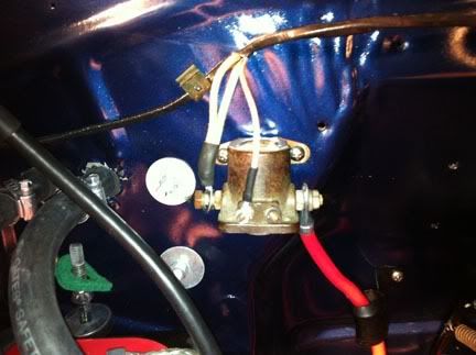
So before I burn something up here is my dilemma. I bought this 1952 F1 in hundred boxes. The wiring harness was suppose to be for 12 volt system. The starter solenoid, starter, regulator, and coil (build in resistor) are 12 VDC. Starter button has two wires going into it.
But I think I am missing a wire or something here on starter solenoid using current harness.
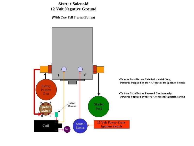
As wire in these pictures... with ignition switch in run mode and pressing starter button the engine will spit and cough but the red wire going to starter will get smoking hot. When I look at posted wiring diagrams (see below) from this site they show a wire going to S terminal and wire going to I terminal on 12VDC system. Currently the small wire on I terminal is going through harness to coil and is only hot with ignition in run mode.
So my question is do I have a 6 volt harness and need to run an additional wire?
Where do I run the wire to?
All help is appreciated. I know enough about the electrical to make me dangerous.
Thanks in advance
But I think I am missing a wire or something here on starter solenoid using current harness.
As wire in these pictures... with ignition switch in run mode and pressing starter button the engine will spit and cough but the red wire going to starter will get smoking hot. When I look at posted wiring diagrams (see below) from this site they show a wire going to S terminal and wire going to I terminal on 12VDC system. Currently the small wire on I terminal is going through harness to coil and is only hot with ignition in run mode.
So my question is do I have a 6 volt harness and need to run an additional wire?
Where do I run the wire to?
All help is appreciated. I know enough about the electrical to make me dangerous.
Thanks in advance
#2
11-09-2012, 08:39 PM

The large terminal on the left should go directly to the battery's positive terminal, assuming you're negative ground.
I would then assume the two white wire on that same terminal should be moved to the small terminal on the front with no wires.
At least that's how mine is.
The solenoid is nothing more than an electric switch, the two terminals in the front activate the switch using a small amount of power that can flow though the starter button without burning it out. The switch allows a large amount of power to go directly from your battery (large left terminal) to your starter (large right terminal), without having to go all the way through the starter and ignition switches.
#3
11-09-2012, 08:42 PM
Welcome to FTE. What engine are you running? Are you trying to use the original starter button? You are missing a wire to the second terminal. You might have the original starter button wire as 6 volt and you might be grounding out the red one to the starter. I'll check my set up tomorrow. I'm sure someone will help you sort it out.
#4
11-09-2012, 09:26 PM
Fleet Owner
The diagram is correct. The "I" terminal on the solenoid is only hot while cranking; it is feeding the coil to bypass the ballast and give a hotter spark for starting. Since you have a coil with internal ballast, there is no way to bypass it, so you don't need anything connected to the solenoid "I" terminal.
The only things that could make your big cable to the starter hot are that it is undersized, or the starter is drawing too much current. Are you cranking for long periods trying to start it? Never crank more than 10 - 15 seconds without waiting at least 30 seconds to a minute before cranking again.
The only things that could make your big cable to the starter hot are that it is undersized, or the starter is drawing too much current. Are you cranking for long periods trying to start it? Never crank more than 10 - 15 seconds without waiting at least 30 seconds to a minute before cranking again.
#5
11-09-2012, 09:30 PM
Elder User
Join Date: Aug 2012
Location: Cuba, AL (NO internet)
Posts: 751
Likes: 0
Received 0 Likes
on
0 Posts
if the large red wire is going to the starter then there should be a heavy gauge wire from the positive side of the battery to the left post. The double white wire stays where it is. You also need a single wire from the alternator to the large left post (same place positive battery will go). My best response with the info so far.
#6
11-09-2012, 09:33 PM
Elder User
Join Date: Aug 2012
Location: Cuba, AL (NO internet)
Posts: 751
Likes: 0
Received 0 Likes
on
0 Posts
#7
11-09-2012, 09:36 PM
Join Date: Oct 2012
Posts: 19
Likes: 0
Received 0 Likes
on
0 Posts
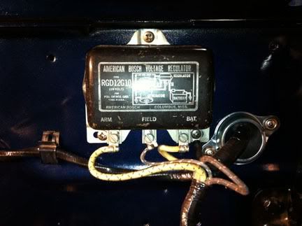
Thanks for responses. The camera flash blurs the wiring colors. The two large wires going to large solenoid battery post are yellow and come from voltage regulator. This seems to be per 1952 electrical diagram. The smaller of these wires actually splices off eyelet and goes to horn relay.
So let me provide some better pictures of wiring colors at button and solenoid. When wiring the inside of cab there were two wires of same color (Red w/Blue tracer) left over at starter button. I assume these both go to button.
On the harness at the outside of firewall I assume because the color of the wire at the "S" terminal (red w/blue tracer) was the same as starter button it would go to S post and because the yellow wires had a large eyelet they would go to large battery post because 1952 manual says they go to large post on relay terminal. Is this thought correct?
Do I need to run a wire from "I" terminal on solenoid relay independantly to + on coil? What am I missing?
I have the positive side of battery disconnect from yellow wire on solenoid relay post so the project doesn't burn the barn down if something is wrong while I am away. I am cranking the engine for ten seconds and having my wife hold the strater wire and watch for smoke. The red wire is getting pretty toasty after three attempts with a cool down cycle. The engine is a 1953 Mercury 255 Stroker Flathead built by Bud Lee.

Starter Button Colors - Red Blue tracer per 1952 wiring manual but there are two of them. manual says one red w Blue and other terminal is grounded. So I am not understanding this.
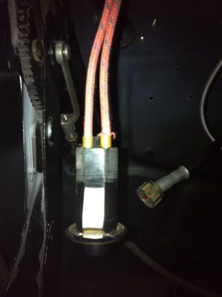
The starter button will only work with (Red w/blue tracer) wires plugged into it. So I am not understanding this because manual shows a ground on one terminal.
The motor is a 1953 mercury Flathead built by Bud Lee. The wife is monitoring the heat at red starter wire and looking for smoke. On three attempts to start with a cool down period the solenoid post at red wire started to smoke alittle and wire was hot. Hence the reason the postive battery terminal is disconnect in the pictures.
So let me provide some better pictures of wiring colors at button and solenoid. When wiring the inside of cab there were two wires of same color (Red w/Blue tracer) left over at starter button. I assume these both go to button.
On the harness at the outside of firewall I assume because the color of the wire at the "S" terminal (red w/blue tracer) was the same as starter button it would go to S post and because the yellow wires had a large eyelet they would go to large battery post because 1952 manual says they go to large post on relay terminal. Is this thought correct?
Do I need to run a wire from "I" terminal on solenoid relay independantly to + on coil? What am I missing?
I have the positive side of battery disconnect from yellow wire on solenoid relay post so the project doesn't burn the barn down if something is wrong while I am away. I am cranking the engine for ten seconds and having my wife hold the strater wire and watch for smoke. The red wire is getting pretty toasty after three attempts with a cool down cycle. The engine is a 1953 Mercury 255 Stroker Flathead built by Bud Lee.
Starter Button Colors - Red Blue tracer per 1952 wiring manual but there are two of them. manual says one red w Blue and other terminal is grounded. So I am not understanding this.
The starter button will only work with (Red w/blue tracer) wires plugged into it. So I am not understanding this because manual shows a ground on one terminal.
The motor is a 1953 mercury Flathead built by Bud Lee. The wife is monitoring the heat at red starter wire and looking for smoke. On three attempts to start with a cool down period the solenoid post at red wire started to smoke alittle and wire was hot. Hence the reason the postive battery terminal is disconnect in the pictures.
Last edited by travelingman55; 11-09-2012 at 09:49 PM. Reason: Additional Information
Trending Topics
#8
11-09-2012, 09:44 PM
Fleet Owner
I bet you are looking at a '51 wiring diagram. In '52 they went to a different solenoid and a starter button with two wire connections, to feed battery power to the S terminal. Your solenoid is an even later one, but functions the same as a '52's. Earlier buttons only had one wire connection, from the S terminal, and grounded that thru the spring clip that holds the button in the dash. Follow the diagram above. Connecting by color may be dangerous, didn't the new harness come with a diagram??
PS -- as Wayne asked above, I'm not seeing the big battery cable from the (+) terminal going to the left big terminal on the solenoid?
Here's a diagram with some enhancements
PS -- as Wayne asked above, I'm not seeing the big battery cable from the (+) terminal going to the left big terminal on the solenoid?
Here's a diagram with some enhancements
#9
11-09-2012, 09:58 PM
Join Date: Oct 2012
Posts: 19
Likes: 0
Received 0 Likes
on
0 Posts
All I got was a bunch of boxes when I bought the truck in Dallas. There was no wiring diagram it came from Antique Auto Supply in Arlington. I am using the 1952 shop manual as a guide but I am not sure if the copy I bought on the internet actually is the 1952 supplement. I appreciate the info on the starter button. Do you have a diagram that shows this?
The gentlemen who owned the truck before me told me he was converting to 12 volt. It is a frame off restoration with no manuals on how to put it back together. Mr. Miller had a stroke and was unable to finish project. I am trying to put the truck together so I can take him for a ride in it. Every night I go out and out a new part on the truck. There are plenty of other areas to work on but i would like to get-r started.
The gentlemen who owned the truck before me told me he was converting to 12 volt. It is a frame off restoration with no manuals on how to put it back together. Mr. Miller had a stroke and was unable to finish project. I am trying to put the truck together so I can take him for a ride in it. Every night I go out and out a new part on the truck. There are plenty of other areas to work on but i would like to get-r started.
#11
11-09-2012, 11:45 PM
Join Date: Oct 2012
Posts: 19
Likes: 0
Received 0 Likes
on
0 Posts
#12
11-09-2012, 11:48 PM
Fleet Owner
#13
11-10-2012, 04:20 AM
#14
11-10-2012, 09:13 AM

Hy, I have a 51 F1 with a flathead 8. It is still on 6 volt. While driving and having the lights on the battery turns empty. I measured the voltage on the battery after 30 miles and it was 3.8 V, when powering up the engine it went to 4 V. Lights were of and the engine was on normal temperature. The generator was rewired so maybe I can do something with the voltage regulator. Can you tell me how to do this?
#15
11-21-2012, 06:25 PM