
No electrical, completely dead, won't start
#46
 07-20-2012, 11:55 AM


#47
07-22-2012, 06:10 PM

Join Date: Jun 2012
Posts: 43
Likes: 0
Received 0 Likes
on
0 Posts


#48
07-22-2012, 06:14 PM
Join Date: Jun 2012
Posts: 43
Likes: 0
Received 0 Likes
on
0 Posts
#49
07-22-2012, 06:28 PM
Join Date: Jun 2012
Posts: 43
Likes: 0
Received 0 Likes
on
0 Posts
The fusible link I replaced was a black wire. The black wire runs off of the rubber tab in the below picture, the black wire has an orange rubber tab on the end of it. The orange rubber tab is on the right side of the picture.
Ford Truck Enthusiasts Forums - View Single Post - No electrical, completely dead, won't start
#50
07-22-2012, 08:24 PM
Join Date: Jun 2012
Posts: 43
Likes: 0
Received 0 Likes
on
0 Posts
If you are not getting 12+ volts on the battery side of the fuse box than try checking the resistance from the battery side of the fuse panel back to the battery. You will have to make some extentions for your probes with some 12 ga wire or larger. If the resistance is high than start tracing wireing back to the battery which I believes goes through the solenoid connections. Can we assume that the truck was originally a single battery system? If not this can add some complexity to the tracing and trouble shooting effort. Hope this helps.
I don't know if the truck was originally a single battery system, I bought the truck from a previous owner. The truck is currently a single battery system.
I don't know how to trace the resistance from the battery side of the fuse box to the battery.
#51
07-22-2012, 08:33 PM
Join Date: Jun 2012
Posts: 43
Likes: 0
Received 0 Likes
on
0 Posts
I don't know if this will help, but the schematic at this link shows 4 fusible links.
http://www.justanswer.com/uploads/cr...ruckwiring.pdf
Also, what is the history of this problem? You say in your initial post it won't start and seems to have no electrical. Is this a thing that started while you were operating the truck, or was it like this when you got the truck?
http://www.justanswer.com/uploads/cr...ruckwiring.pdf
Also, what is the history of this problem? You say in your initial post it won't start and seems to have no electrical. Is this a thing that started while you were operating the truck, or was it like this when you got the truck?
The history of the problem is that the truck just stopped working after I hadn't driven it for a few weeks. The truck was running fine, everything was working fine. I hadn't driven the truck for a few weeks, and it just went completely dead.
#53
07-23-2012, 09:29 AM
Hey sj, Reading back over this thread, I'm a little confused by something. You said in one of the earlier posts:
"Removed the fusible link. There is a wire that connects into the voltage regulator that appears to become one with the fusible link(there is a rubber tab that both the voltage regulator wire and the fusible link join into). On the one end of the fusible link after the rubber tab, there is only wire exiting the rubber tab. On the other end of the fusible link before the rubber tab, the fusible link and the wire running to the voltage regulator are separate."<?xml:namespace prefix = o ns = "urn:schemas-microsoft-com fficeffice" /><o
 ></o>
></o>
You say the fusible link you removed is on a wire that "connects to the voltage regulator and appears to become one with the fusible link." On the wiring schematic I sent you for the 78, (linked here: http://www.justanswer.com/uploads/crazi429/2006-08 30_221853_78fordtruckwiring.pdf) the wire that runs from the voltage regulator to the starter solenoid is yellow where it connects to the regulator and splits into two black/red wires, one of which goes to the starter solenoid and one to the alternator. The fusible link is on this black/red wire between the solenoid and where it splits.
Later a poster asked: "Was the fusible link you replaced in the Black/Yellow wire?" <o></o>
You replied: "Yes, I replaced the fusible link for my charging circuit (the fusible link going to my alternator)." <o></o>
<o> </o>
But, according to my wiring diagram, the fusible link on the circuit going to the alternator (as described by me above) is not Black/Yellow, but Black/Red. <o></o>
<o> </o>
<o> </o>
Then you say, "the fusible link I replaced was a black wire. The black wire runs off of the rubber tab in the below picture, the black wire has an orange rubber tab on the end of it. The orange rubber tab is on the right side of the picture."
When you say "black wire", do you mean it was all, black with a red stripe (what's called a "tracer"), or with a yellow stripe, or which? I know the wiring diagrams, like the one I sent you, are not always accurate on colours, etc.. but I'm just tryign to make sure we understand the situation and rule out the possibility of simple mis-wiring. What colour or colours is the wire you replaced the fuse link on? Where does it come from and go to?
<o></o>
"Removed the fusible link. There is a wire that connects into the voltage regulator that appears to become one with the fusible link(there is a rubber tab that both the voltage regulator wire and the fusible link join into). On the one end of the fusible link after the rubber tab, there is only wire exiting the rubber tab. On the other end of the fusible link before the rubber tab, the fusible link and the wire running to the voltage regulator are separate."<?xml:namespace prefix = o ns = "urn:schemas-microsoft-com
fficeffice" /><o></o>You say the fusible link you removed is on a wire that "connects to the voltage regulator and appears to become one with the fusible link." On the wiring schematic I sent you for the 78, (linked here: http://www.justanswer.com/uploads/crazi429/2006-08 30_221853_78fordtruckwiring.pdf) the wire that runs from the voltage regulator to the starter solenoid is yellow where it connects to the regulator and splits into two black/red wires, one of which goes to the starter solenoid and one to the alternator. The fusible link is on this black/red wire between the solenoid and where it splits.
Later a poster asked: "Was the fusible link you replaced in the Black/Yellow wire?" <o
></o>You replied: "Yes, I replaced the fusible link for my charging circuit (the fusible link going to my alternator)." <o
></o><o
> </o>But, according to my wiring diagram, the fusible link on the circuit going to the alternator (as described by me above) is not Black/Yellow, but Black/Red. <o
></o><o
> </o><o
> </o>Then you say, "the fusible link I replaced was a black wire. The black wire runs off of the rubber tab in the below picture, the black wire has an orange rubber tab on the end of it. The orange rubber tab is on the right side of the picture."
When you say "black wire", do you mean it was all, black with a red stripe (what's called a "tracer"), or with a yellow stripe, or which? I know the wiring diagrams, like the one I sent you, are not always accurate on colours, etc.. but I'm just tryign to make sure we understand the situation and rule out the possibility of simple mis-wiring. What colour or colours is the wire you replaced the fuse link on? Where does it come from and go to?
<o
></o>
#54
01-13-2014, 07:09 PM
Senior User
Join Date: Jun 2012
Location: Boise, ID
Posts: 298
Likes: 0
Received 0 Likes
on
0 Posts
#55
01-27-2016, 07:16 PM

Back from the dead. Troubleshooting what sounds like the same problem. Starter solenoid fried today, replaced it and now have no electrical power. Am able to jump the starter motor but have no power to the key, accessories or fuses. Hopefully will find something soon.
#56
01-28-2016, 02:26 PM
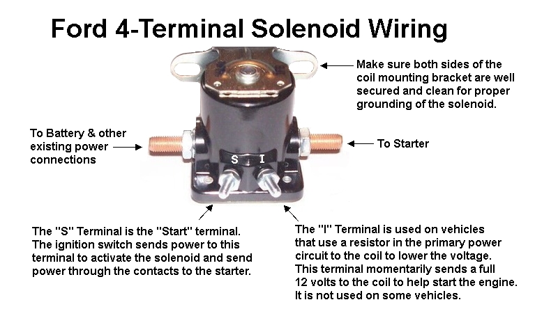
If you've just replaced the solenoid, and now have no power to ANYTHING, check to make sure you've got all the wiring back in like it was before. Battery goes in from the left, with the Black w/ Yellow stripe wire under/over it. Output to the starter motor from the other big terminal (on the right). S & I Terminals hooked up correctly too - getting those backwards will kill the car being able to start (but will let it be cranked with a jumper).
Here's a general guide to tracking down and eliminating electrical problems. You will need several tools/supplies (not all tools required for all jobs, these are just all the tools I've used while repairing my busted '77):
By now, you're probably looking at my list and thinking that either A) I don't have all of these tools, or B) This is going to be tough. I promise, you don't need all of them right away, and it's not nearly as hard as you think. The only things you absolutely NEED are the multimeter, wire, cutters, and either crimps or soldering iron/solder, and basic hand tools (screwdrivers/wrenches). I included all the other stuff just in case you run into a situation where you can't decide what the best approach is, and having a reminder that other solutions exist can be extremely useful! So, here are the basic steps to get started on general trouble.
Section 0 - The absolute basics
So, the big thing we need to know is how we measure and detect electricity. We use two tools to diagnose circuits - Voltage (Volts) and Resistance (Ohms). Voltage is kind of like electrical pressure - higher voltage will jump bigger and bigger gaps (you can lick a 9V battery, don't try licking a 50,000V Stun Gun). Resistance is how hard it is for electricity to get from Point A to Point B (like running through deeper and deeper water/snow).
Voltage is always measured across a (supposedly) powered wire and a ground - so positive on a voltage source (like the + terminal on the battery) and the negative on a ground (like the - terminal on the battery). How much electrical pressure there is will be measured in Volts. Getting 0 Volts can mean several things - a broken wire, a bad ground, corrosion somewhere, or even a dead battery. If you try to measure voltage in line (from one end of a powered wire to another) you'll always get a reading of 0 - one end always has to be on a known good ground!
Resistance is always measured in line. So, one end of a wire gets the positive lead, the other end of the wire gets the negative lead. How hard it is for the electricity to get from one end to the other is measured in Ohms (note that almost all multimeters have settings for Kilo-Ohms and Mega-Ohms - so make sure you're in the correct range bracket - .1Ohm is very different from .1KOhm!). If there is no electrical path present, your meter may show "OL" or "OPEN" which means there's no connectivity at all (i.e. Broken wire, or trying to measure one end of wire A with the other end of wire B). If you go across two wires, or from a wire to a ground, there's a chance you will see a path if the electricity can somehow flow between the two points (backtracking to the fuse box, then out the second wire to where you're testing, or even through a component like a sensor!) Because of this, it's very important to make sure you've got the right wires.
Section 1 - No Start/No Electrical
So, at this point, the truck should crank over when you jumper the S & I terminals. That's good, and it means that we know the battery, main power & ground wires, and starter motor are all good. If that fixed a problem you were having before, please verify that the remaining electrical circuits are still working (lights, radio, etc). Now, assuming something else isn't working, it gets a little more tricky.
Generally speaking, there's only two things you can do to diagnose circuits. Check for voltage at the destination, and check for continuity between two points. If there's no voltage between a wire that's supposed to carry power and a known good ground, then you need to move back upstream in the circuit, and try again - or try a different grounding point!
Section 2 - Troubleshooting general electrical problems/no power anywhere in the truck
If you're testing a circuit that's not the headlights, you need to go through a different chain. Test the Circuit, then Test the fuse and fuse box.
So basically, you just have to check for voltage, and if you don't have it, trace back a step up the chain and check again. Keep doing this until you find a point that has power. At that point, look for a corroded connection, broken wire, or burnt out fusible link, and repair/replace as necessary. I used the example of the headlight switch because I know for a fact the headlight switch is supposed to have power all the time - so if you've got power to the headlight switch, everything else should be pretty simple (and inside the cab!)
Here's a general guide to tracking down and eliminating electrical problems. You will need several tools/supplies (not all tools required for all jobs, these are just all the tools I've used while repairing my busted '77):
- Multimeter - Must read Ohms (1-1000), Volts (DC, .1 - 50), and have a continuity buzzer (for hard to reach places where you can't see the meter)
- Multimeter Probes - spike/probe style are usually included with the multimeter, and clip on (alligator jaw) are a plus and can free up a hand.
- Clip Leads (Also called test leads) - with alligator Jaws on them - Various colors.
- Screwdrivers (Phillips & Flathead)
- Basic small socket set for taking off body bolts & grounds)
- Small wire brushes - steel & brass
- Coils of wire - Red, Black, Green, Orange, Yellow in 18ga
- Coils of wire - Red & Black in 12/14ga for bigger accessories (heater blower, etc)
- Wire Cutters
- Wire Strippers/Crimp tool (easier than using wire cutters)
- Various Crimps - Butt, Ring Lug, "Finger Style" (prong?), Bullet connectors
- Dielectric grease (small tube)
- Soldering Gun (or iron, guns heat up faster and are better for quick intermittent use)
- Solder - Get electronics solder with a rosin core
- Assorted sizes of heat shrink tube (smaller stuff is more useful)
- Heat Gun
- Fuses, Assorted sizes/capacities based on what your vehicle uses
- A bright flashlight - a AA LED Maglite is awesome, you can hold it in your mouth while upside down under the dash.
By now, you're probably looking at my list and thinking that either A) I don't have all of these tools, or B) This is going to be tough. I promise, you don't need all of them right away, and it's not nearly as hard as you think. The only things you absolutely NEED are the multimeter, wire, cutters, and either crimps or soldering iron/solder, and basic hand tools (screwdrivers/wrenches). I included all the other stuff just in case you run into a situation where you can't decide what the best approach is, and having a reminder that other solutions exist can be extremely useful! So, here are the basic steps to get started on general trouble.
Section 0 - The absolute basics
So, the big thing we need to know is how we measure and detect electricity. We use two tools to diagnose circuits - Voltage (Volts) and Resistance (Ohms). Voltage is kind of like electrical pressure - higher voltage will jump bigger and bigger gaps (you can lick a 9V battery, don't try licking a 50,000V Stun Gun). Resistance is how hard it is for electricity to get from Point A to Point B (like running through deeper and deeper water/snow).
Voltage is always measured across a (supposedly) powered wire and a ground - so positive on a voltage source (like the + terminal on the battery) and the negative on a ground (like the - terminal on the battery). How much electrical pressure there is will be measured in Volts. Getting 0 Volts can mean several things - a broken wire, a bad ground, corrosion somewhere, or even a dead battery. If you try to measure voltage in line (from one end of a powered wire to another) you'll always get a reading of 0 - one end always has to be on a known good ground!
Resistance is always measured in line. So, one end of a wire gets the positive lead, the other end of the wire gets the negative lead. How hard it is for the electricity to get from one end to the other is measured in Ohms (note that almost all multimeters have settings for Kilo-Ohms and Mega-Ohms - so make sure you're in the correct range bracket - .1Ohm is very different from .1KOhm!). If there is no electrical path present, your meter may show "OL" or "OPEN" which means there's no connectivity at all (i.e. Broken wire, or trying to measure one end of wire A with the other end of wire B). If you go across two wires, or from a wire to a ground, there's a chance you will see a path if the electricity can somehow flow between the two points (backtracking to the fuse box, then out the second wire to where you're testing, or even through a component like a sensor!) Because of this, it's very important to make sure you've got the right wires.
Section 1 - No Start/No Electrical
- Verify the problem. What circuit isn't working (or are all of them dead?).
- Using a clip lead (or a screwdriver, in a pinch), temporarily jumper the "S" and "I" terminals on the solenoid. The solenoid should click, and the engine should crank. Remove clip lead. Skip the remainder of this section/list.
- Set your multimeter to DC Volts. Check for Voltage across the battery. If the voltage is present, keep going. Otherwise, charge your battery for a few hours and retest. (Check for voltage while charging - if your meter shows no voltage during charging, check your meter before continuing). Nominal battery voltage is 12.6V at rest, and 13.5V with the motor running.
- Verify all of your primary connections - Multimeter to Ohms, check from the negative battery terminal to the engine block mounting point. Meter should read "0" ohms - meaning perfect electrical conductivity. If it reads more than .1 Ohms, repair as follows.
- Remove both ends of the ground wire, clean with the wire brushes (wire ends AND mounting points), apply a VERY THIN layer of dielectric grease, and reinstall both ends. If you don't have dielectric grease, just clean them and then wipe them down before reinstallation. Check again for resistance between the motor and battery. If it still reads high, replace the ground wire.
- Check for Voltage on the starter solenoid. Multimeter to DC Volts, and put the positive (red) lead on the input side of the solenoid, and the negative (black) lead on the battery ground (or engine block). This voltage should be identical to the battery voltage (12.0V+).
- If the battery side shows no voltage, set your meter to Ohms and check the battery cable - should be 0 Ohms, just like the ground strap. Repair is identical - clean, reinstall, retest, replace if needed.
- Using a clip lead (or a screwdriver, in a pinch), temporarily jumper the "S" and "I" terminals on the solenoid. The solenoid should click, and the engine should crank. Remove clip lead
- If the engine doesn't crank and the solenoid doesn't click, re-attach a clip lead between the "S" and "I" terminals
- Check for voltage passthrough on the other side of the solenoid (should be the other big wire that goes to the starter motor) with the negative lead still on the ground. This should ALSO read identical to battery voltage (12.0V+)
- If you read battery voltage, immediately remove the S & I jumper to avoid melting wires. Replace the starter motor and retest.
- If the starter side showed no voltage with S & I jumpered, set your meter to Ohms, and check for resistance across the solenoid. The big terminals on either side of the solenoid should have 0 Ohms with S & I jumpered. If not, and it reads lots of resistance, replace the solenoid.
So, at this point, the truck should crank over when you jumper the S & I terminals. That's good, and it means that we know the battery, main power & ground wires, and starter motor are all good. If that fixed a problem you were having before, please verify that the remaining electrical circuits are still working (lights, radio, etc). Now, assuming something else isn't working, it gets a little more tricky.
Generally speaking, there's only two things you can do to diagnose circuits. Check for voltage at the destination, and check for continuity between two points. If there's no voltage between a wire that's supposed to carry power and a known good ground, then you need to move back upstream in the circuit, and try again - or try a different grounding point!
Section 2 - Troubleshooting general electrical problems/no power anywhere in the truck
- Verify the fuse for the circuit is good - multimeter on ohms, across the fuse, or pull it and visually inspect it.
- Verify the ground in the circuit you're testing. Multimeter to Ohms, and check from the wire to the body ground, and then from the wire to the chassis ground (engine block and/or battery). Both of these should read 0 Ohms or .1 Ohms. If you really want to eliminate the ground from the equation, use a clip lead from the negative battery terminal to a long piece of wire run all the way around into the cab, and use that as your "known good" ground - just attach the wire to the negative meter terminal with another lead.
- If the ground is bad, figure out why - is the body ground corroded or loose? Clean with a wire brush, apply dielectric grease, and retighten. If the body ground has a clean connection (0 Ohms) to the chassis ground, figure out why the wire isn't making good connection - is it corroded, frayed, kinked?
- Next, verify the 12V source is supplying power to the circuit. If the headlights aren't working, for example, pull the dash bezel, remove the headlight switch's plug, and check for 12V in the pins.
- If you find 12V in the appropriate pins (wiring/switch diagrams are available online for free), replace the switch and test for circuit operation
- If you don't find 12V in any of the pins on the plug, you need to go one step further up the chain - normally for a circuit it would be the fusebox (and then the ignition switch), but for the headlight switch, there is a fusible link right near the starter solenoid
- On a 79, the wire on the starter solenoid is black with a yellow stripe, and should connect to the battery side of the starter motor solenoid. Test this wire by using a clip lead from the ring lug, to a length of wire stretched out to the cab, and then to the power supply pin for the headlight switch (hint - it's the biggest wire going up to the switch!). You need to have 0 Ohms on this wire. If it reads "OL" or "OPEN" then the fusible link is bad and needs to be replaced. DO NOT CRIMP THE NEW ONE IN. I know that the new fusible links generally come with crimps on them...cut them off and solder the wire, if at possible, and then use THREE layers of heat shrink tubing (you have to do one at a time, and you need to put the pieces onto the wire before you solder them). Crimps allow water into the wire, and over time the wire will corrode, and then fail again. A good solder job with the right size heat shrink tubing will be waterproof for as long as you want to own the truck!
- Test to verify the wire now has continuity (no resistance).
- Reinstall the Headlight switch and test circuit function.
If you're testing a circuit that's not the headlights, you need to go through a different chain. Test the Circuit, then Test the fuse and fuse box.
- Verify the fuse is still good, and then test to see if you have 12V on either side of the fuse (or any of the fuses)
- If no 12V at the fuses in the fuse box, check the supply wire to the fuse box - it should have 12V.
- If the 12V supply wire does have voltage, then you need to disconnect the battery, remove the supply wire, clean all the contacts (including the fuse holders!), and reinstall. If that doesn't fix it, replace the fuse box.
- If the 12V supply wire to the fuse box does not have voltage, trace the wire back to the ignition switch. Remove the ash tray to get a little better access to the back of the switch, and then pull the connector off the back. Inspect the connector to make sure it's not scorched/burnt, and that there are no loose wires going into it. (One wire feeds one side of the fuse box for the accessory position, another feeds during the on/run position).
- Make sure that the ignition switch has 12V coming into it from the battery. If it does, and there's no voltage output, remove the switch from the dash. Using your key, turn the switch through the various positions and verify that there is continuity (0 ohms) between the supply pin and the outputs. If the switch doesn't put power to the right pins in the right position, replace the switch.
- If the switch ohms out ok (0 ohms across different pins in various positions), and there's no power coming into the switch, trace the wire back out. This shares the fusible link that's on the Black wire w/ yellow stripe that connects to the starter solenoid's BATTERY SIDE that we talked about in the headlight section. Verify this is good and not burnt out, replace as needed.
- Re-Test, congratulations, if you followed all of the steps, you should have power at your circuit.
So basically, you just have to check for voltage, and if you don't have it, trace back a step up the chain and check again. Keep doing this until you find a point that has power. At that point, look for a corroded connection, broken wire, or burnt out fusible link, and repair/replace as necessary. I used the example of the headlight switch because I know for a fact the headlight switch is supposed to have power all the time - so if you've got power to the headlight switch, everything else should be pretty simple (and inside the cab!)
#57
05-16-2016, 10:39 AM
Join Date: Jun 2012
Posts: 43
Likes: 0
Received 0 Likes
on
0 Posts
FWIW, I forgot to post, back in 2012, that I finally got my truck running again.
Another poster, TonyS., just had the same problem, and we were able to get his truck running again too. See the below thread link:
https://www.ford-trucks.com/forums/1...ont-start.html
What happened was that the connector on the end of one of the wires, the black and yellow wire, just got worn out I guess and fell off somehow and became disconnected, so, the black and yellow wire was just dangling unconnected to anything. I had no idea if that wire was supposed to be connected to anything or not.
I could not decipher the wiring diagram myself, so I had to have my uncle, who is an excellent mechanic that lives an hour away, decipher the wiring diagram. After the wiring diagram was deciphered, I was able to get that wire reconnected properly, and that fixed the entire problem.
That one wire being disconnected disabled the entire truck, the truck had no power at all when that wire was disconnected.
#58
05-18-2016, 02:54 PM
FWIW, I forgot to post, back in 2012, that I finally got my truck running again.
...
What happened was that the connector on the end of one of the wires, the black and yellow wire, just got worn out I guess and fell off somehow and became disconnected, so, the black and yellow wire was just dangling unconnected to anything. I had no idea if that wire was supposed to be connected to anything or not.
I could not decipher the wiring diagram myself, so I had to have my uncle, who is an excellent mechanic that lives an hour away, decipher the wiring diagram. After the wiring diagram was deciphered, I was able to get that wire reconnected properly, and that fixed the entire problem.
That one wire being disconnected disabled the entire truck, the truck had no power at all when that wire was disconnected.
If you had checked for resistance between both ends of that wire (the connector that was loose, and anywhere else after the fusible link) you would've found it - you were so close to diagnosing it on your own!-Brad
#59
05-19-2016, 06:51 PM
Join Date: Jun 2012
Posts: 43
Likes: 0
Received 0 Likes
on
0 Posts
No, it was not the fusible link that got disconnected. The black and yellow wire was not the fusible link.
I replaced the fusible link because I thought the fusible link might be the problem, but the new fusible link did not fix the problem.
The problem is that if a wire gets disconnected, and you have no idea what that wire is supposed to be connected to, and you can not decipher a wiring diagram, then you are screwed.
#60
05-20-2016, 02:54 PM
Directly coming from the top of the starter motor relay (found in block C-4), wire #37 is Black w/ Yellow Stripe, and immediately after the starter solenoid, has the fusible link in it.
In your picture, found here:

The black wire with the yellow stripe (#37) has a little black lump in it. That little black lump is the fusible link. If one end of that wire wasn't connected, the whole link won't have power.
EDIT: Also - with the way the wires are pulled tight on the battery side of the starter relay, you'll have another failure at *some* point in the future (It might be in two months, may be in 5 years). The wires should have enough slack so that they can move a little bit without any strain on the connectors. The exposed copper bits may also speed up corrosion, which might make the problem re-surface (even though everything will "seem" to be good).

Thread
Thread Starter
Forum
Replies
Last Post
kacpam
1980 - 1986 Bullnose F100, F150 & Larger F-Series Trucks
4
06-09-2003 09:17 AM
jwinsor
Electrical Systems/Wiring
4
02-03-2002 01:13 PM