Glow plug relay's and utter confusion and loss
#1
 07-25-2011, 03:53 PM


Join Date: Jul 2011
Posts: 94
Likes: 0
Received 0 Likes
on
0 Posts
Glow plug relay's and utter confusion and loss
1990 7.3 idi in an F250
I've posted on this in a different thread but I'm not getting replies, which may be because its the sort of questions better suited to this part of the forum.
Here's the condensed version of my dilemma.
Glow plugs all test good. And I have a manual GP button in the dash along with a push start button next to it.
I've had the relay out, and here it is.......
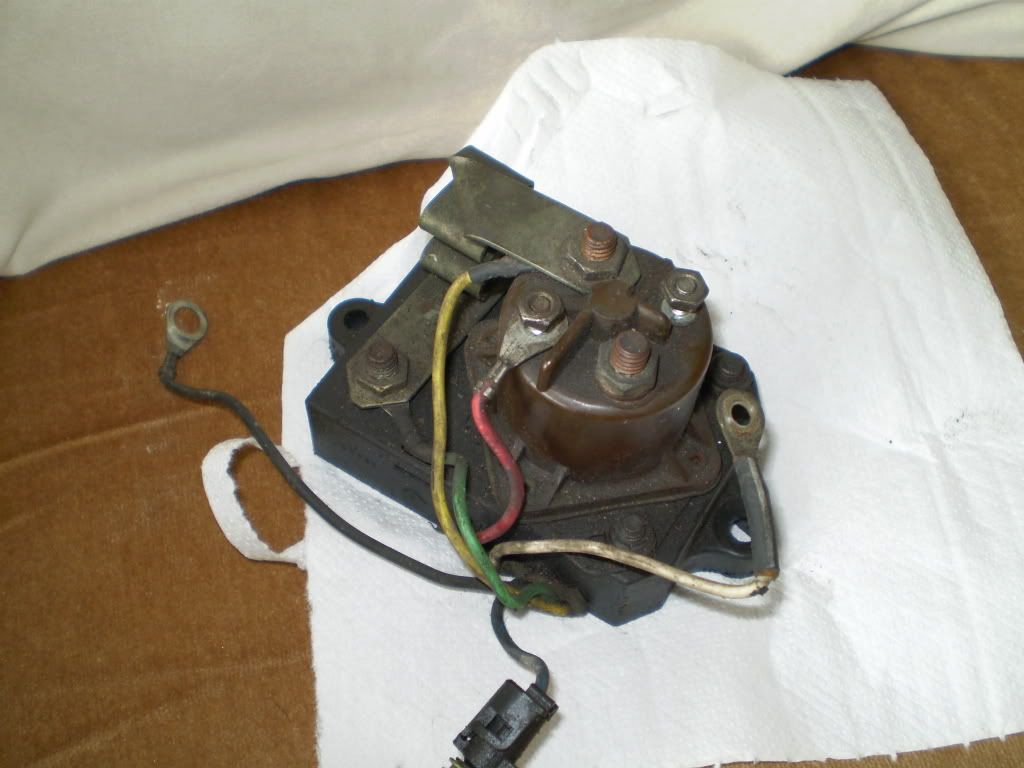
I cleaned it up ready to go back in.
I found this wired up behind it though..........
... Which I have identified as an independent solenoid/relay for the GP's, similar to that on the CUCV's. Trouble is I un-wired it when removing the other relay ( and GP loom ) and I forgot how it was wired in.
I also un-wired the GP button in the cab as it was a terrible mess of poor wiring ( multiple bad connectors used, frayed wires etc ).
I tried wiring the GP factory relay but I can't get the truck fired up on it, the WTS light stays on for about 6 seconds or so, but the voltage meter on the dash doesn't move. Then you need a lot of 'easy start' ( not sure what its known by in the states, but thats what it is here in the U.K ) and cranking to get the beast to fire up.
So I have been researching and studying up on these relays for days now, but there is little visual explanations available and a lot of conflicting opinions.
Today I spent the morning researching, and the afternoon crawling all over the engine bay. I tried to do a manual wire up of the relay, with one terminal on the button going to the post on the relay where the white wire would be, had I not removed it as per instruction. The other terminal on the button is well grounded. The result is a little drop in voltage when you press it for a split second, then no voltage drop at all.
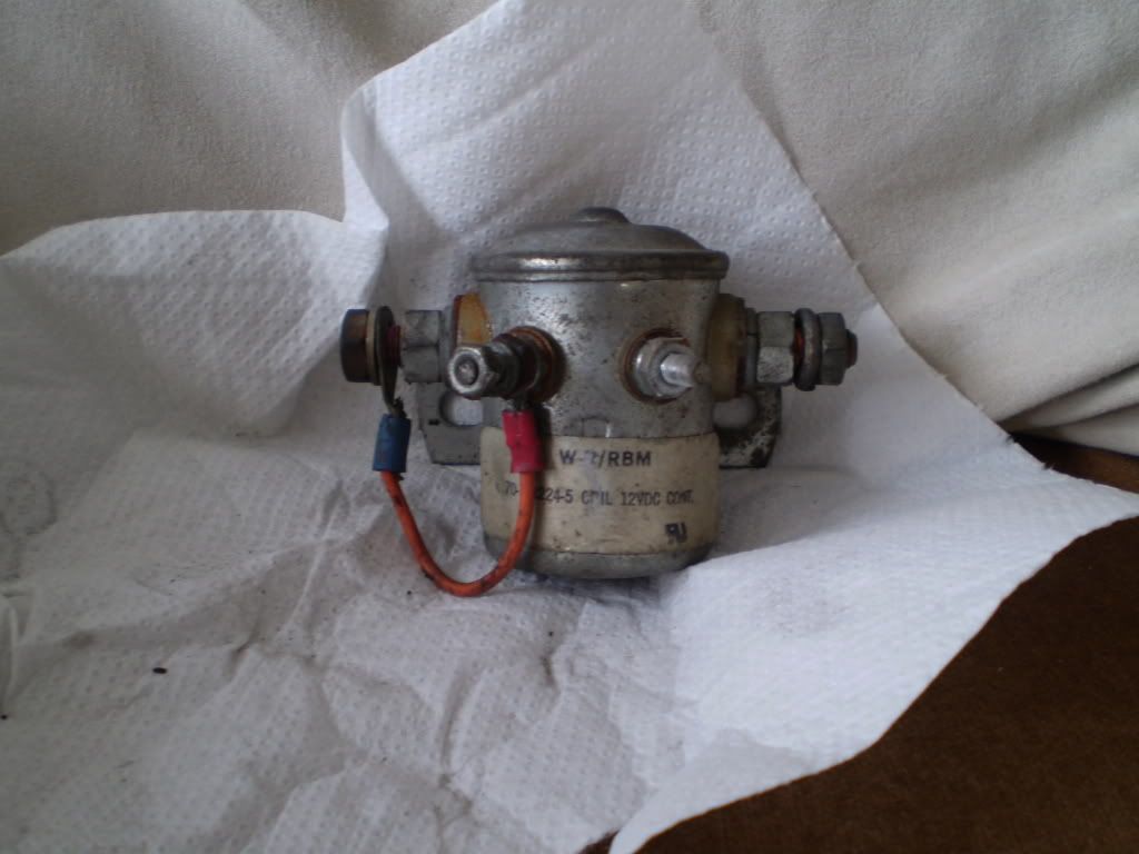
I tried all the other ways for a manual set up, no results. I tried to work out how to wire up the cucv type 4 post relay/solenoid ( as in the picture ) but I got no results off that either.
So first question is, how are you supposed to wire up this cucv type aftermarket solenoid/relay ? It must be easy, but I can't work it out and I can't find a drop of usable info on the net even after days of trying. I just get reams of " buy this Glow plug " or " buy a new relay. But I am certain others must have one of these 4 post cucv thingys on their idi's ?
The next question is obvious, why can I get little and then no voltage out of the factory fit relay, or has it long died ( and the other 4 post thing is its replacement maybe ) ?
And lastly, a slightly different issue, ( from yesterday ) the start button was trouble free all day, then for some reason its now clicking the starter solenoid, but takes repeated pressing before it cranks. I've checked the wiring to the starter and nothing has changed, so any thoughts on why the solenoid is kicking in fine but only 1 out of 10-15 tries will it crank the engine ?
Any one out there at all that can help ? I have a major project for the next 4 weeks ( which started yesterday ) and the very first darn day the truck starts letting me down badly after I have been crawling all over it since I got it two weeks ago
Thanks everyone ! Really hope someone can help on at least one or two things ! It would be really appreciated !
I've posted on this in a different thread but I'm not getting replies, which may be because its the sort of questions better suited to this part of the forum.
Here's the condensed version of my dilemma.
Glow plugs all test good. And I have a manual GP button in the dash along with a push start button next to it.
I've had the relay out, and here it is.......
I cleaned it up ready to go back in.
I found this wired up behind it though..........
... Which I have identified as an independent solenoid/relay for the GP's, similar to that on the CUCV's. Trouble is I un-wired it when removing the other relay ( and GP loom ) and I forgot how it was wired in.
I also un-wired the GP button in the cab as it was a terrible mess of poor wiring ( multiple bad connectors used, frayed wires etc ).
I tried wiring the GP factory relay but I can't get the truck fired up on it, the WTS light stays on for about 6 seconds or so, but the voltage meter on the dash doesn't move. Then you need a lot of 'easy start' ( not sure what its known by in the states, but thats what it is here in the U.K ) and cranking to get the beast to fire up.
So I have been researching and studying up on these relays for days now, but there is little visual explanations available and a lot of conflicting opinions.
Today I spent the morning researching, and the afternoon crawling all over the engine bay. I tried to do a manual wire up of the relay, with one terminal on the button going to the post on the relay where the white wire would be, had I not removed it as per instruction. The other terminal on the button is well grounded. The result is a little drop in voltage when you press it for a split second, then no voltage drop at all.
I tried all the other ways for a manual set up, no results. I tried to work out how to wire up the cucv type 4 post relay/solenoid ( as in the picture ) but I got no results off that either.
So first question is, how are you supposed to wire up this cucv type aftermarket solenoid/relay ? It must be easy, but I can't work it out and I can't find a drop of usable info on the net even after days of trying. I just get reams of " buy this Glow plug " or " buy a new relay. But I am certain others must have one of these 4 post cucv thingys on their idi's ?
The next question is obvious, why can I get little and then no voltage out of the factory fit relay, or has it long died ( and the other 4 post thing is its replacement maybe ) ?
And lastly, a slightly different issue, ( from yesterday ) the start button was trouble free all day, then for some reason its now clicking the starter solenoid, but takes repeated pressing before it cranks. I've checked the wiring to the starter and nothing has changed, so any thoughts on why the solenoid is kicking in fine but only 1 out of 10-15 tries will it crank the engine ?
Any one out there at all that can help ? I have a major project for the next 4 weeks ( which started yesterday ) and the very first darn day the truck starts letting me down badly after I have been crawling all over it since I got it two weeks ago
Thanks everyone ! Really hope someone can help on at least one or two things ! It would be really appreciated !
#2
07-25-2011, 05:41 PM

Read the sticky posts at the top of this forum. The go into detail about both types of glow plug systems.
Are your batteries still charged? They might be low from you messing around with it. Also don't crank the start for a long length of time. Its either 15 or 30 seconds MAX (can't remember what everyone recommends) then 2 minutes of cool down time. It could just be that your starter is getting tired and needs replacing, that will make a HUGE difference in starting.
Are your batteries still charged? They might be low from you messing around with it. Also don't crank the start for a long length of time. Its either 15 or 30 seconds MAX (can't remember what everyone recommends) then 2 minutes of cool down time. It could just be that your starter is getting tired and needs replacing, that will make a HUGE difference in starting.
#3
07-25-2011, 05:46 PM
Join Date: Jul 2011
Posts: 94
Likes: 0
Received 0 Likes
on
0 Posts
Thanks for the reply !
I can safely say that the starter was replaced no more than a year ago, batteries holding charge at around 13 volts. As I say, no voltage drop on the dial when the glow plugs should be coming on, or when I press the button. And I always crank for a maximum of 15 seconds then a 2 minute minimum cool down time. I wonder if my start button has started giving up on me, I'll try fitting another one asap to test that theory. And I'll ake a look at the stickies now, thanks very much !
I can safely say that the starter was replaced no more than a year ago, batteries holding charge at around 13 volts. As I say, no voltage drop on the dial when the glow plugs should be coming on, or when I press the button. And I always crank for a maximum of 15 seconds then a 2 minute minimum cool down time. I wonder if my start button has started giving up on me, I'll try fitting another one asap to test that theory. And I'll ake a look at the stickies now, thanks very much !
#4
07-26-2011, 03:45 AM

Hey budddy.
after some online work, and a few phonecalls, I`we found this for you.
these guys are 110% carguys, and well worth both time and money.
They stayed after hours, just so I could get a few items for my 1980 buick.
not to mention, the fact, they were on the phone with me, the whole time, until I found the shop, (got lost a few times, since I didn`t have a working GPS)
They didn`t try to sell me stuff I didn`t need, and more than once, they told me to where to get cheaper parts.
They have also a huge positive reputation on the biggest amcar forum in Norway.
I dont know if they speak english, but if they dont, just send me a mail, and I`ll translate it, and forward it to them!
Sarpsborg Motor AS
Jan
#5
07-26-2011, 04:29 AM


Okay to make this easy for you!!! The brown relay is (probably bad , hence why it was bypassed) that seems like a feeble/remedial attempt to do so!!! So ditch it and go to the parts store and get a new one!! So just to clear up your manual GP wiring , the red wire needs to be hot with the ignition on and the other small post goes to the dash switch and then to a clean ground source!!! Thats all there is to it!!!
Duralast/Relay - Glow Plug (F494) | 1986 Ford F250 3/4 ton P/U 4WD 8 Cylinders 1 6.9L Diesel | AutoZone.com
Duralast/Relay - Glow Plug (F494) | 1986 Ford F250 3/4 ton P/U 4WD 8 Cylinders 1 6.9L Diesel | AutoZone.com
#6
07-30-2011, 02:07 PM
Join Date: Jul 2011
Posts: 94
Likes: 0
Received 0 Likes
on
0 Posts
A big thanks for the help and research and so on, I really appreciate it ! 
I'm having a super busy week so I'm slow on getting replies up and shopping around for a relay. I'm sure the relay is dead because its wired up and when first pressed the voltage drops a little for that brief moment, then never again until the ignition is turned off then on again.
Its a shame because I could really do with that silver solenoid/relay working right so I can at least heat manually, but though I understand that the ignition ( hot ) line goes one side and the GP loom on the other, I'm not getting what the other two small posts are for.
I've tried the manual button on the post ( and grounded the other terminal on the switch ) but it blows the in line fuse, I've tried direct off the battery, different grounding points etc, its as though the other smaller terminal should be used somehow, maybe the live wire for the button ? I just can't work it out. I wish I had just a diagram of the solenoids innards so I can see which terminal/post does what on it.
So I'll keep shopping around for a new relay at least.
I am still having trouble with the alternator, my batteries gave out again a couple of days ago. I was using the truck to haul some things around a building site ( not in an abusive way I should add, I am very careful with my beasty ) and I think due to idling all the time I lost charge after a few start ups. So I've still to get a bigger alternator.
And finally my TPS is still not right. I've tried both the old and the new, set at 1.20volts idle and its max for fully open throttle ( about 4.10 volts at best ) but when driving I still get heavy gear shifts ( its the E4OD by the way ) and on about 70% throttle or more it changes up not down and/or just can't decide what gear to go for and starts losing itself until I ease right off the throttle again. Am I missing something here with setting the TPS or something ?
My many many thanks again !
#7
07-30-2011, 04:10 PM
Posting Guru
Join Date: Feb 2011
Location: Princeton MN
Posts: 2,216
Likes: 0
Received 0 Likes
on
0 Posts

Trending Topics
#8
07-30-2011, 04:22 PM
Join Date: Jul 2011
Posts: 94
Likes: 0
Received 0 Likes
on
0 Posts
Thanks for that, I appreciate you pulling up that image.
Thats how I am wired up right now. Its that silver relay/solenoid that I want to work out because I know it works ( and the original relay does not ), but I don't know what each post is for ( or I should say where to attach what wires too ).
The manual button is wired in as well, but again, the original ( brown ) relay is obviously near dead, so I only get a momentary burst of power until it shuts off again.
I've spent days trying to find out how this silver relay should wire up so I can at least use that for the time being because I'm still having to start the truck with easy start which I really do not like doing.
I know these same silver 4 post relays are used on military Ford trucks and the like, but I can't find an image or diagram anywhere on how they wire up to the 7.3's GP loom. And I don't like the idea of a trial and error method to much
Thanks again for the help and replies, I really do appreciate it.
#9
07-30-2011, 04:27 PM
#10
07-30-2011, 04:33 PM
Join Date: Jul 2011
Posts: 94
Likes: 0
Received 0 Likes
on
0 Posts
I wish it was as easy as that, I really do. But half my battle is not having any suppliers in the U.K. I can't even find anything close. From the states is a good week or so to get the parts and shipping is high ( we are talking at least $50 + in total ) and from other sources in Europe, it costs even more sadly.
I'd like to be able to heat my plugs with something before the truck gets addicted to easy start.
I'd like to be able to heat my plugs with something before the truck gets addicted to easy start.
#11
07-30-2011, 05:44 PM
Posting Guru
Join Date: Feb 2011
Location: Princeton MN
Posts: 2,216
Likes: 0
Received 0 Likes
on
0 Posts
Here across the pond on a normal relay, the "s" terminal would be the signal wire or trigger wire, and the "I" terminal should cover your WTS light.
My best guess is with your gray relay the small terminal with the red wire is your "S" and the other one is your "I". Battery power comes in on the big lug with the wire and hook your glowplugs to the other lug. I'd do this only to get by til you get the correct relay.
So get power to your manual button then from the button to the "S" terminal this should trigger the relay
Last edited by 84-6.9L; 07-30-2011 at 05:46 PM. Reason: More info added
#12
07-30-2011, 06:24 PM
With that silver relay, if you put 12v across the 2 smaller terminals, it connects the 2 larger terminals together. So, if you connect 1 large terminal to battery+, the other large terminal to your glow plugs, one small terminal to ground (some are grounded internally, so use a continuity tester to see if one of them is grounded to the mounting frame...), the other small terminal to one side of your manual glow plug button, and the other side of the glow plug button to battery+, then the button will close the relay and connect the glow plugs to battery+.
#13
07-30-2011, 07:18 PM
Posting Guru
Join Date: Feb 2011
Location: Princeton MN
Posts: 2,216
Likes: 0
Received 0 Likes
on
0 Posts
With that silver relay, if you put 12v across the 2 smaller terminals, it connects the 2 larger terminals together. So, if you connect 1 large terminal to battery+, the other large terminal to your glow plugs, one small terminal to ground (some are grounded internally, so use a continuity tester to see if one of them is grounded to the mounting frame...), the other small terminal to one side of your manual glow plug button, and the other side of the glow plug button to battery+, then the button will close the relay and connect the glow plugs to battery+.
#14
07-31-2011, 09:43 AM
Join Date: Jul 2011
Posts: 94
Likes: 0
Received 0 Likes
on
0 Posts
Thanks for the info on that, its really really helpful !I wish I had taken a picture before unwiring the relay's. I know that before I ripped it out I would still get the usual WTS light and hear the relay, so somehow both were operating I think ( seems illogical though ). But that info really helps anyway.
I tried it with the main power feed going in on the left fat post of the silver relay, and GP's off the other side with the fused + from the manual button to the left hand smaller post, but nothing on the other post. Instead I earthed off the other terminal on the button to the chassis. That must be why it was still not working right. I need to earth the smaller post directly, and I assume still earth the other terminal on the manual button ?
I'm still a little eluded bythat orange wire on the silver relay though as it effectively connects the main power feed to that smaller post ( as seen in the pic ), but as said, that means the smaller terminal ( where I'd place the manual button + wire ) would be continuously powered I'd guess ? But it was working wired like that before. Bit confusing that one.
Anyway I'll give it a try over the next day or so, see what happens while I continue to try and source a relay at a fair price ( as always its the shipping that costs so much ).
Just to check, is it often that the controller itself packs up ? Or is it a near certainty that its the relay on the unit that has gone ? I just thought best to check before I buy.
Thanks ever so much again everyone, its a great help !
#15
07-31-2011, 12:17 PM
There are different ways a solenoid (relay) can be wired. Some are grounded (earthed) through the mounting bracket. Some are not, and require one of the small terminals to be grounded to complete the circuit. It sounds like thats how your silver one is made. The orange wire provided constant power to the smaller terminal. The manual button must have gone to ground to fire off the relay.
If you have a multimeter you can check for continuity between the two small terminals. If they are connected, one side is for 12V, the other for ground (earth). If they are not connected, but one of them is connected to the metal mounting bracket, you have the kind that 84-6.9L is talking about. Either kind can work for this situation, it just depends on how its wired up.
To answer your question about the relay vs controller, I don't really know, but the relay is the cheaper fix. You should be able to test either the silver one, or the brown one on the controller (disconnect other wires first). Connect 12V to one of the small terminals, and ground the other. If the relay clicks, it probably works. Test the resistance between the two big terminals when its powered to see. Its possible that the connections inside have gotten burnt out or corroded over time, so even if it clicks, it may not be able to pass sufficient voltage to work the glow plugs.