
Taurus Fan Installation
#61
 02-01-2011, 10:03 PM


According to the eBay link you provided the switch runs HI at 180 degrees.
Josh
#63
02-01-2011, 10:03 PM

#65
02-01-2011, 10:06 PM
#66
02-01-2011, 10:22 PM
Here is a link to the wiring you can find a pic on the 16th post
http://www.utahstangs.org/forum/inde...howtopic=19233
The only diff in our application is you would wire 86 to 12v+ switched, no diodes, run terminal 85 on the first relay to low on the temp switch, and terminal 85 on the second relay to high on the temp switch.
http://www.utahstangs.org/forum/inde...howtopic=19233
The only diff in our application is you would wire 86 to 12v+ switched, no diodes, run terminal 85 on the first relay to low on the temp switch, and terminal 85 on the second relay to high on the temp switch.
#68
02-02-2011, 02:38 AM
#69
02-02-2011, 06:03 PM
Lead Driver
There is soooooo much wrong where to begin?
On the 1st Relay the led is ON when the toggle switch is OFF, ummm ok.
On the 2nd relay, the temp switch is doing what? Nothing, unless there is + going to it, or it needs to be ran as the ground on 86.
The "probe" engages Hi speed which seems counter productive, if anything the LOW speed should be temp controlled and HIGH speed should be manual.
Also, HIGH speed is going to blow those relays in no time.
The key is finding a dual temp sending unit that has the on-off qualities you desire. Then use that to trigger each respective relay.
So say 195 on 185 off and 220 on 200 off should be safe to keep the high speed and low speed seperate.
Josh
Some of us around here (ME!) are electrical MORONS and have to rely on others for things of this nature. I looked at that diagram and saw nothing wrong, but that is because I don't know crap about wiring other than if you tell me what goes where I can do a very clean job of running it.
While I can fabricate and melt metal a bit I'm pretty dumb when it comes to motors in general, wiring and a few other automotive related things others on here know like the back of their hand. That's why I will ask for an explanation when I don't get/understand something I see or give one if someone else asks about somethnig I am familiar with. This is what makes this an informative forum!

#70
02-02-2011, 06:40 PM
I was thinking about this thread while walking my dog after work...
I can visualize how to run a temp controlled low speed with a toggled hi speed, just need to draw it up somehow.
Basically it uses a relay as the switch to either run the low speed circuit HOT at all times or switch it with a toggle to trigger the HI speed relay.
Josh
I can visualize how to run a temp controlled low speed with a toggled hi speed, just need to draw it up somehow.
Basically it uses a relay as the switch to either run the low speed circuit HOT at all times or switch it with a toggle to trigger the HI speed relay.
Josh
#71
02-02-2011, 07:34 PM
#72
02-02-2011, 08:23 PM

#73
02-02-2011, 08:59 PM
I'm not a fan of the diagram in question either. If I'm not mistaken it shows the fan on low as long as the ignition is on. That seems pointless or lazy to me and there's no way I would run that kind of power through those relays. Josh is absolutely right to use a heavy solenoid to switch the fan on.
So anyway, I picked up two of these and two 3G's today.
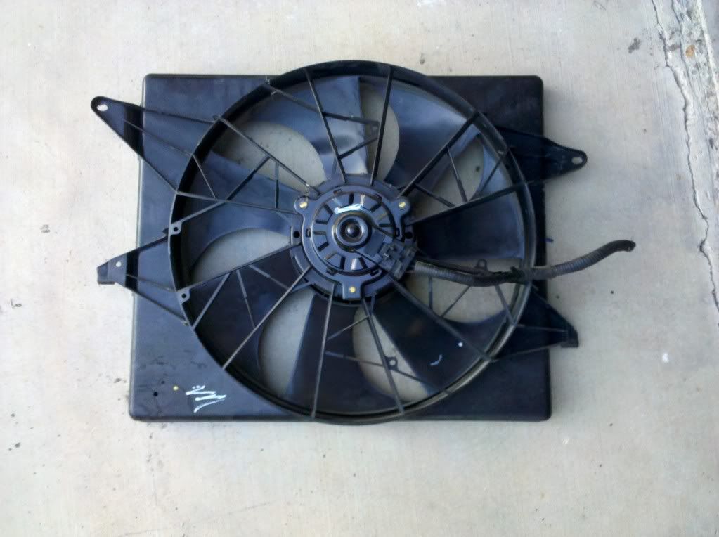
I talked to my parts guy and he suggested using two generic thermo switches of different temps to trigger the relays. Cole/Hersee has lots of them in their marine catalog for triggering lights and alarms on boats. These would make the wiring clean and simple since you could keep all the hot wires near the relays close to the power source and to run two ground wires over to the switches on the engine.
Good info about the marine switches. Where would you plug them into the coolant?
#74
02-02-2011, 09:11 PM
I'll try to explain, I don't have a premium account so I can't post a diagram.
Relabel your high relay #1 and low #2, run a wire from terminal 87 on the #1 relay to 30 on #2 . Nothing on #1 relay 87a.
On relay #2 87a goes to low speed fan, 87 to high speed fan.
85 on both relay 1 and 2 to 12v+ keyed switched. 86 on relay #1 goes to low fan control.
86 on relay #2 to high fan control.
Now if you buy the audi fan control, label it 1-2-3. it is a 3 pole control. terminal #2 goes to ground. 1 goes to #86, #1 relay. 3 goes to #86, #2 relay.
When that control reaches 88C it energizes #1 relay turning on low speed fan. when it gets up to 93C it energizes #2 relay activating high speed fan with both relays energized.
I hope you can follow? It is very simple. no diodes, no leds, no manual switches. And best of all, fully automatic operation.
#75
02-02-2011, 09:23 PM