Converting to an altrnator
#31
 01-03-2011, 05:43 PM


Ok, so I've been looking over this schematic for a 1956 truck (taken from Ealr's World -- thanks George);

The only issue that I can see is that it appears as if the original idiot light has constant power to it. It looks as if the ignition switch feeds the headlight switch (#18 B-G wire) to the "B" terminal of the headlight switch
It would be better if the idiot light had switched power to it, that way in case something goofy happened to the internal regulator it wouldn't cause a drain on the battery.
This should be easy to verify. I'm guessing you don't have either a voltmeter or testlight since you say that electrical ain't your game. Do you have a buddy with some electrical sense? tools? You can build your own test light easy enough, all you need is a 12V bulb and a couple of lenths of wires. An old parking light bulb works good for this. Tape or solder the one wire to the side of the bulb and the other to the bottom lead nub of the bulb. Strip a short length of the other end of the wires and Ta-Dah, instant test light. Verify that it works by touching one wire to either side of the battery (light should come on).
Now, locate the regulator (black box approx 3"x4" with several wires) typically mounted on the firewall. The terminals should be labeled something like "B", "F", and "A". I think that the wire on the "B" terminal should be yellow (see schematic above). With the key off touch one end of the test light to the bolt holding the regulator to the firewall and the other wire to the yellow wire on the "B" terminal.
Is the light on or off?
Now turn the key on and check it again
is the light on or off?
Hopefully the light is off with the key off and on with the key on, even if its on in both positions the new alternator will work but you run the risk of having a draw on the battery. This would be easy to fix by changing the feed to the idiot light under the dash from a constant 12V source to a switched source.
Do some more reading on those links I posted. That guy gives a pretty good description of the basic workings of it all.
Hope this helps some
Bobby
#32
01-03-2011, 08:50 PM
OK, maybe I'm not that electrically-dumb then. I have a few testing lights, a multimeter, and have done some simple wiring before.....I just have trouble making sense of wiring diagrams and where to plug what wire.
Things are making more sense, and I'll start the whole conversion process tomorrow morning.
Thanks a ton everyone for helping, especially Ross and Bobby, awesome help.
Things are making more sense, and I'll start the whole conversion process tomorrow morning.
Thanks a ton everyone for helping, especially Ross and Bobby, awesome help.
#35
01-04-2011, 03:08 AM

At the risk of making this another headache. But it was easier...
I did a little research and decided against a 1 wire system (not really very good systems) and a 3 wire (too much clutter and the box on the fender and the wires) and settled on a 12SI GM alternator. Technically, it's a 2 wire and a diode. It fit in the bracket I got from Speedway, I snagged a 12SI from the junkyard and the heavy gauge wire from the alternator up the harness (the pigtail), took it home, replaced the front bearing and the rectifier transistor in the back of the housing because I got it wet. Cleaned it, painted it, put it in.
They look like this

Mine is wired like this
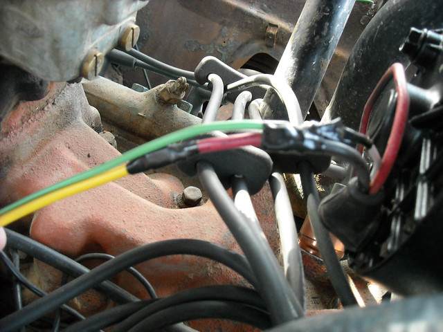
Green wire is from pin 1 on the plug to ignition switch on the 12V side of the ballast resistor and has a cheap diode from radio shack in it (prevents feedback to the ignition circuit - if you don't have it or a heavy load indicator light on it, your ignition won't shut off. I just soldered it in line with the silver ring closer to the alternator and heat shrunk tubing on it). Red wire goes from pin 2 on the plug to the BAT post. Yellow wire is from the BAT post to the to the starter solenoid hot side. That's all there is to it. The diode is a generic 12V dc diode. Any 12V DC diode will work. I dug thru the box at radio shack and found the heaviest gauge wire on the leads but it doesn't matter. All a diode does is allow current to flow in only one direction. That way current flows to the field side of the alternator but doesn't flow back to the ignition circuit when the key is off.It's not on the road, but it works fine and charges well.
I ended up hacking off a little bit of the long side of the alternator body to fit the bracket correctly to line up with the pulleys on the engine, but no worries. I used some heavy brass tubing and made a collar for the bolt on the other side and such to get it all purty. If you are interested, I can take more pics and show you how it's setup. My alternator is a 63 amp alternator. Because the simplicity of the circuit, I don't worry about burning up anything else in the wiring. The only power from the alternator goes to the fat terminal on the solenoid.
Oh, here's the diagram and how to.
GM Alternator Conversion Info - Mustang Forums at StangNet
and a pic

As an aside, the 12SI is a better designed unit. The power it makes is a much cleaner and more stable signal (for them computers, but it works fine on flatheads) It provides higher amperage and can do it for sustained periods of time because of the better cooling design. Also, nothing but 2 little wires come off of it and can be cleanly routed next to the head or around the distributer and down so they become almost invisible. Mine are just laying there because I am in the middle of a project and haven't decided where everything goes yet. Also, it is very easy to change the guts out if I decide to and get an easy 120 amps or more if I want to later.
For my alternator, new bearing (I used a 12 ton press and a gentle hand to remove and replace the bearing) new rectifier and diode, I think I was out about $20. I got a little piece of brass pipe from lowe's plumbing department for a few bucks. I also used an impact wrench to pull the serpentine pulley off and put on a v belt pulley from an old alternator laying on the floor of my shed.
Lastly, the little bit I cut off the front housing was only about 1/4" It ended up making the end of the long side of the alternator level with the back of the front housing. It sounds weird writing it but I just trimmed a bit off till the pulleys lined up and sanded and cleaned it up to get the hacksaw marks off.
They look like this
Mine is wired like this
Green wire is from pin 1 on the plug to ignition switch on the 12V side of the ballast resistor and has a cheap diode from radio shack in it (prevents feedback to the ignition circuit - if you don't have it or a heavy load indicator light on it, your ignition won't shut off. I just soldered it in line with the silver ring closer to the alternator and heat shrunk tubing on it). Red wire goes from pin 2 on the plug to the BAT post. Yellow wire is from the BAT post to the to the starter solenoid hot side. That's all there is to it. The diode is a generic 12V dc diode. Any 12V DC diode will work. I dug thru the box at radio shack and found the heaviest gauge wire on the leads but it doesn't matter. All a diode does is allow current to flow in only one direction. That way current flows to the field side of the alternator but doesn't flow back to the ignition circuit when the key is off.It's not on the road, but it works fine and charges well.
I ended up hacking off a little bit of the long side of the alternator body to fit the bracket correctly to line up with the pulleys on the engine, but no worries. I used some heavy brass tubing and made a collar for the bolt on the other side and such to get it all purty. If you are interested, I can take more pics and show you how it's setup. My alternator is a 63 amp alternator. Because the simplicity of the circuit, I don't worry about burning up anything else in the wiring. The only power from the alternator goes to the fat terminal on the solenoid.
Oh, here's the diagram and how to.
GM Alternator Conversion Info - Mustang Forums at StangNet
and a pic
As an aside, the 12SI is a better designed unit. The power it makes is a much cleaner and more stable signal (for them computers, but it works fine on flatheads) It provides higher amperage and can do it for sustained periods of time because of the better cooling design. Also, nothing but 2 little wires come off of it and can be cleanly routed next to the head or around the distributer and down so they become almost invisible. Mine are just laying there because I am in the middle of a project and haven't decided where everything goes yet. Also, it is very easy to change the guts out if I decide to and get an easy 120 amps or more if I want to later.
For my alternator, new bearing (I used a 12 ton press and a gentle hand to remove and replace the bearing) new rectifier and diode, I think I was out about $20. I got a little piece of brass pipe from lowe's plumbing department for a few bucks. I also used an impact wrench to pull the serpentine pulley off and put on a v belt pulley from an old alternator laying on the floor of my shed.
Lastly, the little bit I cut off the front housing was only about 1/4" It ended up making the end of the long side of the alternator level with the back of the front housing. It sounds weird writing it but I just trimmed a bit off till the pulleys lined up and sanded and cleaned it up to get the hacksaw marks off.
#36
01-04-2011, 06:44 AM
If, when you go to install the GM style alternator, you find it to be "clocked" wrong (the terminals and rear mounting point don't line up with anything or are in the way) you can remove the 4 perimeter bolts and rotate the rear body of the alternator to a better position....you have 4 choices.
Bobby
Bobby
#37
01-04-2011, 09:38 AM

Senior User
Join Date: Jan 2004
Location: Albany NY
Posts: 298
Likes: 0
Received 0 Likes
on
0 Posts
Ok, so I've been looking over this schematic for a 1956 truck (taken from Ealr's World -- thanks George);
The only issue that I can see is that it appears as if the original idiot light has constant power to it. It looks as if the ignition switch feeds the headlight switch (#18 B-G wire) to the "B" terminal of the headlight switch
It would be better if the idiot light had switched power to it, that way in case something goofy happened to the internal regulator it wouldn't cause a drain on the battery.
This electrical schematic is found in the back of the 56 Shop Manual (p.424) and it is incorrect!
 The wire shown as 18 ga. B-G between the headlight switch and the ignition switch AM terminal is actually 14 ga. yellow and is the power feed to the ignition switch. The wire shown as 14 ga. Y from the ACC ignition switch terminal is the power feed to the gauges and is actually 18 ga. B-G (black/green).
Furthermore, this schematic is for the "heavy duty" trucks which had an amp meter. The 56 pickups had an idiot light. The wiring details for the idiot light are found in the 56 Shop Manual p. 355. It is an ungrounded lamp wired between the ignition (#18 B-G) and the ARM terminal of the voltage regulator (#18 Y-B).
#38
01-04-2011, 10:43 AM
Everybody keeps showing and telling to hook up terminal#2 directly to the BATT bolt on the alt, but that is technically incorrect. The sad thing is, is that the result may be the same exact performance issues as a generator--worse performance at idle like dim headlights and such.
If this doesn't make sense, maybe go back and read the whole article. I would have never guessed the voltage regulator was this sophisticated....this article really helped me out a lot.
Tken about 1/3 the way down from this page: http://www.madelectrical.com/electri...reewire3.shtml
If you hook up terminal#2 directly to the back of the alt, it will take it's sample from there, meaning that by the time you have reached the junction--on this truck being the starter solenoid--and have turned on your lights, heater fan, etc....you'll be way down in power.....
But if you were to hook up the wire at the junction, these problems may not exist, or at least not as severely.
If this doesn't make sense, maybe go back and read the whole article. I would have never guessed the voltage regulator was this sophisticated....this article really helped me out a lot.
Tken about 1/3 the way down from this page: http://www.madelectrical.com/electri...reewire3.shtml
Value of Remote Voltage-Sensing with THREE-WIRE
The well laid-out factory system will have the voltage regulator taking the “VOLTAGE SENSING” sample directly from the “MAIN JUNCTION,” through a wire dedicated to this function. And that was true with both the external and the internal voltage regulator systems.
As lighting or any accessories are switched ON, more power is drawn from the main junction, which would lower voltage at the junction. But the voltage regulator will increase alternator output as needed to maintain the 14 volt level at the junction. If we have a 2.5 volt drop in the wire between the alternator and the junction, then the voltage regulator will make the alternator produce 16.5 volts to compensate for the voltage drop with routing of power to the junction.
It’s a somewhat “spongy” system, but it does work well and the alternator doesn’t know the difference. Expect bright lights, strong ignition, powerful accessories, and a properly charged battery when this system is wired effectively. When running with the factory-original type wire harness, clearly it is an advantage to maintain the “MAIN POWER DISTRIBUTION JUNCTION” at 14 volts.
But if you were to hook up the wire at the junction, these problems may not exist, or at least not as severely.
#39
01-04-2011, 12:29 PM
This electrical schematic is found in the back of the 56 Shop Manual (p.424) and it is incorrect! The wire shown as 18 ga. B-G between the headlight switch and the ignition switch AM terminal is actually 14 ga. yellow and is the power feed to the ignition switch. The wire shown as 14 ga. Y from the ACC ignition switch terminal is the power feed to the gauges and is actually 18 ga. B-G (black/green).
Furthermore, this schematic is for the "heavy duty" trucks which had an amp meter. The 56 pickups had an idiot light. The wiring details for the idiot light are found in the 56 Shop Manual p. 355. It is an ungrounded lamp wired between the ignition (#18 B-G) and the ARM terminal of the voltage regulator (#18 Y-B).
The wire shown as 18 ga. B-G between the headlight switch and the ignition switch AM terminal is actually 14 ga. yellow and is the power feed to the ignition switch. The wire shown as 14 ga. Y from the ACC ignition switch terminal is the power feed to the gauges and is actually 18 ga. B-G (black/green).Furthermore, this schematic is for the "heavy duty" trucks which had an amp meter. The 56 pickups had an idiot light. The wiring details for the idiot light are found in the 56 Shop Manual p. 355. It is an ungrounded lamp wired between the ignition (#18 B-G) and the ARM terminal of the voltage regulator (#18 Y-B).
dmptrkr,
Thanks for clearing that up. Thats great info!
morotbreath,
I worked as GM mechanic for lots of years, numerous makes and models that GM produced had the #2 wire going straight to the BAT post at the back of the alternator. With any type of chargine system; alternator or generator, Ford, GM, or other you will have less performance at idle than while at RPM, for the most part its not an issue. As was mentioned earlier, sometimes on the earlier alternators you had to rev the idel up after starting to get the alternator up and running. Again, not typically a problem as its very rare to start and engine and just let it idle without any increase at all (it doesnt take much)
Don't get caught up in overthinking this, just jump in there and make it happen....lol
Bobby
#40
01-04-2011, 01:14 PM
^
Yeah, sort of typical.
I took the alt and attempted to mock it up on my other 223. The bracket needs to be a little more than an inch further forward. I contacted "fixnair" on here as he is local and has welding skills, asking him if he would help me fabricate one.
The ball is rolling, and hopefully this will be done in the next week or so, depending on how hard this bracket will be to make.
Thanks a ton everyone!
#41
01-04-2011, 02:09 PM
#42
01-04-2011, 02:37 PM
Fleet Owner
Do a search, someone on here did it about ~4 yrs ago on a 223.
Madison Ave Electric is who I was referring to when I said one particular website is always ranting about the need for a 3-wire. If you really want to eliminate any problems, then run the #2 to the ignition switch -- poof! You're done. Like I said, my experience is like Bobby's, just not a problem for our trucks. If I had an EFI 5.0 with HID headlights and miles of wire, I'd think about it a little more. I don't notice any headlight flare even with my warm idle set to 450 RPM. Comparing it to a POS generator that TOTALLY cuts out of the circuit below ~700 is not accurate.
edit: I thought MAD Enterprises is Madison Ave, maybe not. From his website it is clear he's an electrical purist, no harm in that but you have to put everything in context.
#43
03-02-2011, 02:42 AM
Well alright, I think it's about time to finally do this.
The last main issue was a fuse, so I asked Albuq(Ross) and he advised I buy on of these, but it doesn't look right. Is this the kind of fuse I need between my alt and battery?

Also, will the BATT light work properly with the alt? I don't see why not, but I don't see a lot of things when it comes to electronics...
Thank you all very much.
The last main issue was a fuse, so I asked Albuq(Ross) and he advised I buy on of these, but it doesn't look right. Is this the kind of fuse I need between my alt and battery?
Also, will the BATT light work properly with the alt? I don't see why not, but I don't see a lot of things when it comes to electronics...
Thank you all very much.
#44
03-02-2011, 01:29 PM
Logistics Pro
I did a little research and decided against a 1 wire system (not really very good systems) and a 3 wire (too much clutter and the box on the fender and the wires) and settled on a 12SI GM alternator. Technically, it's a 2 wire and a diode. It fit in the bracket I got from Speedway, I snagged a 12SI from the junkyard and the heavy gauge wire from the alternator up the harness (the pigtail), took it home, replaced the front bearing and the rectifier transistor in the back of the housing because I got it wet. Cleaned it, painted it, put it in.
They look like this
Mine is wired like this
Green wire is from pin 1 on the plug to ignition switch on the 12V side of the ballast resistor and has a cheap diode from radio shack in it (prevents feedback to the ignition circuit - if you don't have it or a heavy load indicator light on it, your ignition won't shut off. I just soldered it in line with the silver ring closer to the alternator and heat shrunk tubing on it). Red wire goes from pin 2 on the plug to the BAT post. Yellow wire is from the BAT post to the to the starter solenoid hot side. That's all there is to it. The diode is a generic 12V dc diode. Any 12V DC diode will work. I dug thru the box at radio shack and found the heaviest gauge wire on the leads but it doesn't matter. All a diode does is allow current to flow in only one direction. That way current flows to the field side of the alternator but doesn't flow back to the ignition circuit when the key is off.It's not on the road, but it works fine and charges well.
I ended up hacking off a little bit of the long side of the alternator body to fit the bracket correctly to line up with the pulleys on the engine, but no worries. I used some heavy brass tubing and made a collar for the bolt on the other side and such to get it all purty. If you are interested, I can take more pics and show you how it's setup. My alternator is a 63 amp alternator. Because the simplicity of the circuit, I don't worry about burning up anything else in the wiring. The only power from the alternator goes to the fat terminal on the solenoid.
As an aside, the 12SI is a better designed unit.
I absolutely agree!!
I am doing the same thing except I just dropped on over to Autozone and bought a 100A 12si right off the shelf!! (I also added a 2-groove drive pulley)
Here it is bolted to my 292 using Vintage Air brackets.....

It's a "3-wire" unit but you don't have to wire it in a 3-wire configuration if you don't want to. It's "idiot-light " capable if you want to use it too.
Cheers,
Rick
