Instructions to hook up Stock 56 Horn
#1
 11-13-2010, 05:31 PM


Join Date: Dec 2009
Location: Austin Texas
Posts: 189
Likes: 0
Received 0 Likes
on
0 Posts
Instructions to hook up Stock 56 Horn
I finally got around to working on the horn today, only to find that there is nothing under the horn button but the "Horn Button Support cup" and "Button Retainer Bell Spring" to hold the horn button on. I am going to order the missing parts from MidFifty, but was wondering if anyone has a picture or drawing of how these all go together?
- Horn Button Contact Spring
- Horn Button Wire, Insulator & Contact
- Horn Button Brass Contact Cap
#2
11-13-2010, 08:11 PM

This post is probably not much help, but it will bump you back up to the top for night shift. 
https://www.ford-trucks.com/forums/9...y-for-12v.html
https://www.ford-trucks.com/forums/9...y-for-12v.html
#3
11-13-2010, 08:30 PM

Post Fiend
Hi there - horny devil!
Here's a couple pictures that will help:
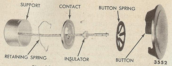
The round "retaining spring" fits into the slots in the "support." The horn wire and insulator fit through the hole in the "contact," then the pointed tabs of the "button spring" fit under the tip of the horn button wire as well.
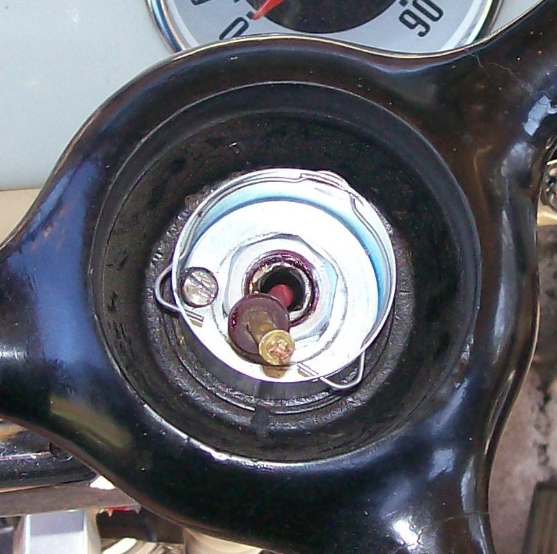
The slotted machine screw you see in the picture above is not OEM. I put that there and it screws into the threaded "puller" hole in the steering wheel. It is to prevent the cup from turning if the steering wheel retaining bolt loosens it's grip on the cup.
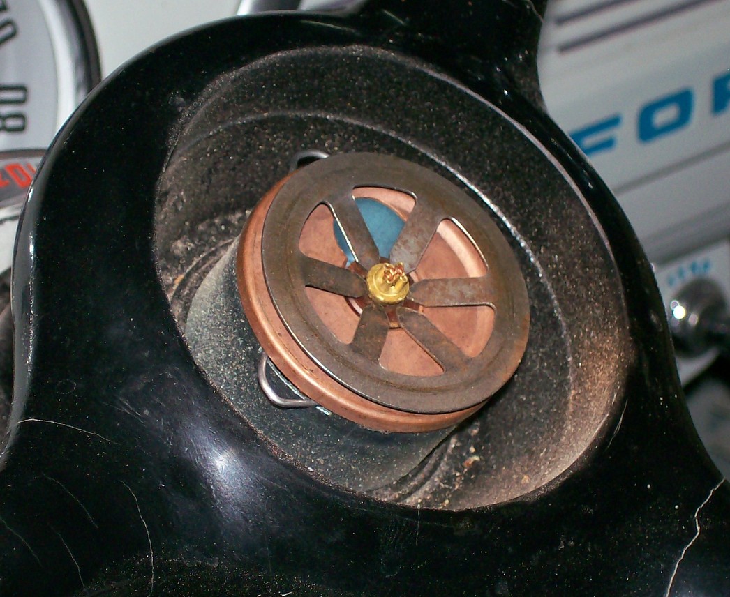
The horn botton (the one shown is 48-52) then gets pushed down and twisted on so "bayonet lugs" inside the horn button fit over then twist behind the three ends of the "retaining spring" that are sticking out of the sides of the "support."
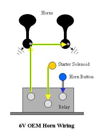
The wire comes out the bottom of the steering wheel shaft at the bottom of the steering box and attaches to the horn relay as shown below. Power comes in from the Starter Solenoid Power terminal (the same one the POSITIVE battery cable is attached to)
Then the connections at the horn relay look like this (6 and 12 volt hook ups are the same).
Let me know if you need more info!
Here's a couple pictures that will help:
The round "retaining spring" fits into the slots in the "support." The horn wire and insulator fit through the hole in the "contact," then the pointed tabs of the "button spring" fit under the tip of the horn button wire as well.
The slotted machine screw you see in the picture above is not OEM. I put that there and it screws into the threaded "puller" hole in the steering wheel. It is to prevent the cup from turning if the steering wheel retaining bolt loosens it's grip on the cup.
The horn botton (the one shown is 48-52) then gets pushed down and twisted on so "bayonet lugs" inside the horn button fit over then twist behind the three ends of the "retaining spring" that are sticking out of the sides of the "support."
The wire comes out the bottom of the steering wheel shaft at the bottom of the steering box and attaches to the horn relay as shown below. Power comes in from the Starter Solenoid Power terminal (the same one the POSITIVE battery cable is attached to)
Then the connections at the horn relay look like this (6 and 12 volt hook ups are the same).
Let me know if you need more info!
#4
11-13-2010, 09:45 PM
Join Date: Dec 2009
Location: Austin Texas
Posts: 189
Likes: 0
Received 0 Likes
on
0 Posts

#5
09-10-2020, 09:58 AM

#7
09-12-2020, 12:02 PM

Thread
Thread Starter
Forum
Replies
Last Post
mdula
1987 - 1996 F150 & Larger F-Series Trucks
38
02-11-2012 01:00 PM
john smith jr
1948 - 1956 F1, F100 & Larger F-Series Trucks
11
10-13-2008 10:33 AM
dcubedus
1967 - 1972 F-100 & Larger F-Series Trucks
11
03-24-2007 05:56 AM