I would recommend that you connect them to the alternator and regulator!
Ok now that you are ready to slap me, I'll give you the bad news. If your regulator has BAT, FLD and ARM on it, it is a regulator for a generator not an alternator. I hope you weren't thinking of using the existing generator regulator with the alternator. That's a "no-no."
Alternator regulators from Ford should have four posts. They are marked "B" (for Battery, or possibly "A" for Alternator Power) "F" (for Field); "S" (for Stator); and "I" (for Ignition). The back of the alternator should likewise be labelled (Batt, F, S....No I) next to the appropriate lugs.
Here is a generic drawing I drew up and another posted some time ago by another member. Take your pick!
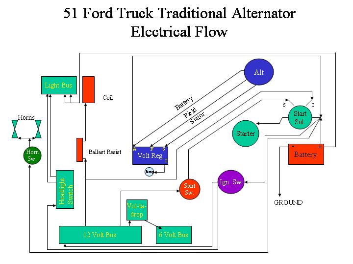
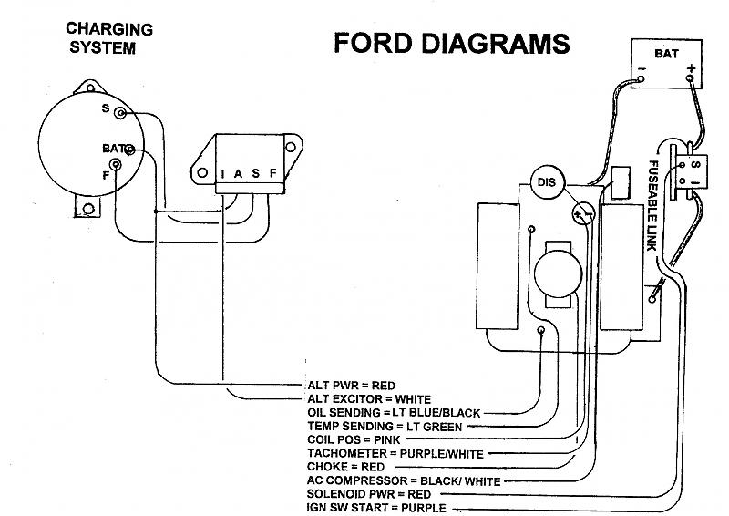
Connect "S" terminal on the Alternator regulator to the "S" (or possibly STA[T]) terminal on the alternator
Connect the "F" terminal on the Alternator regulator to the "F" (or possibly FLD) terminal on the alternator
In the drawings, the "Alt Power" (or Battery) wire coming off the battery lug on the alternator, and co connected to the "A" terminal on the Alternator regulator ends up on the "Batt" terminal of the Ignition Switch - if you have the stock "Amp" guage. Then there is a wire that runs from the "Batt" terminal of the Ignition Switch through the Ammeter indiction loop and ends up on the "Batt" post of the Starter Solenoid. The "I" terminal on the regulator is not used when wired like this.
If you have a Volt meter or "Batt" light, the red wire runs directly to the "Batt" terminal of the Starter Solenoid, and the wire from the "I" terminal runs to the "Batt" light or Volt meter.
I'm assuming this truck has been converted to 12 volt negative ground and you have some other points for power distribution (like a fuse block or the ignition switch) that you are using to distribute power out, and not using the stock 6 volt 30 and 15 amp circuit breakers located on the instrument panel (Which is where the power wire would have gone from the generator regulator "Batt" terminal in a stock 6 volt generator set-up.)
Glad you asked?
