
DIR Flasher
#1
 08-29-2010, 01:18 PM


Join Date: Apr 2009
Posts: 30
Likes: 0
Received 0 Likes
on
0 Posts
DIR Flasher
I have a 1991 f-250 with a 460. On my wiring digram the oxygen sensor has a wire that says it goes to the DIR flasher. Anybody know what that is? where it goes? Im getting ready to transplant the motor into my 1975 f-250 and am trying to make sure i know where all the wiring goes to before i start. Thanks in advance.
After some searching i know what the dir flasher is. Could someone please explain to me why the oxygen sensor is tied into it?
After some searching i know what the dir flasher is. Could someone please explain to me why the oxygen sensor is tied into it?
#2
08-29-2010, 01:35 PM

Join Date: Sep 2006
Location: Long Beach, Calimexiforia
Posts: 6,859
Received 497 Likes
on
253 Posts
I have a 1991 f-250 with a 460. On my wiring digram the oxygen sensor has a wire that says it goes to the DIR flasher. Anybody know what that is? where it goes? Im getting ready to transplant the motor into my 1975 f-250 and am trying to make sure i know where all the wiring goes to before i start. Thanks in advance.
After some searching i know what the dir flasher is. Could someone please explain to me why the oxygen sensor is tied into it?
After some searching i know what the dir flasher is. Could someone please explain to me why the oxygen sensor is tied into it?
#3
08-29-2010, 01:40 PM
Join Date: Apr 2009
Posts: 30
Likes: 0
Received 0 Likes
on
0 Posts

#5
08-29-2010, 02:34 PM
Join Date: Apr 2009
Posts: 30
Likes: 0
Received 0 Likes
on
0 Posts
#7
08-29-2010, 03:19 PM
Join Date: Apr 2009
Posts: 30
Likes: 0
Received 0 Likes
on
0 Posts
i cant figure out how to get from paper to computer file.
purple/orange- Dir flasher
grey/lt blue-pin 29 computer HEGO
black- ground
orange-pin 49 computer HEGO ground as well as self test output, idle air bypass valve, map, maual lever position sensor, transmission, coolant temp sensor, air charge temp sensor, egr
i got the shared grounds, the o2 ground, the o2 signal input, still confused on dir flasher
Trending Topics
#8
08-29-2010, 07:09 PM

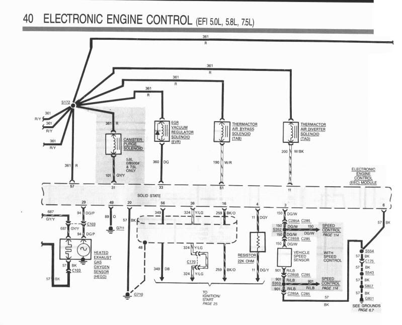
Here's the schematic of the oxygen sensor for a 88. It appears the wiring is
similar to your 91. The 88 has no self test wire.
Bottom left corner shows the heated oxygen sensor.
On the 88 it uses a 3 wire sensor.
The output of the oxygen sensor goes to pin 29 of the computer.
In the schematic it's a Dark Green/Purple wire.
The ground for the oxygen sensor is the body of the sensor which screws
into the exhaust pipe bung. The ground for the heater circuit is a Black wire.
In your case the sensor has 2 ground wires. You can tie them together and
ground them.
The 12 volts for the heater element comes from the ignition switch.
When the ignition switch is in Run/On 12 volts passses thru the ignition switch and provides
12 volts to two circuits.
12 volts goes to Fuse #5 which is the Turn signal flasher.
12 volts also goes to a 20 gauge fusible link and then to the heating
element of the oxygen sensor via a Gray/Yellow wire.
#9
08-29-2010, 09:22 PM
Join Date: Apr 2009
Posts: 30
Likes: 0
Received 0 Likes
on
0 Posts
#10
08-29-2010, 09:37 PM

Thread
Thread Starter
Forum
Replies
Last Post