Flathead buddies and Julie
#16
 06-23-2010, 02:07 PM


Post Fiend
OK Found the problem from pics Larry sent me. This wasn't visible in the first few but I picked it up with the last pic - its at the very top:
Larry, your gauge cluster already has a 12 volt to 6 volt reducer on it for all the gauges. That is that little cube on the cluster. See your last pic below:
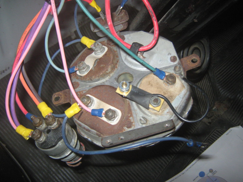
I can't see it but I'm guessing that the darker blue wire that is running power to your gas and oil gauges is attached to the other end of that cube. The red wire is supplying 12 volt power into the cube from the ignition switch and the blue wire is 6 volt power out to the gauges.
So, now that you have changed your 12 volt TEMP sender to a 6 volt, that kills one of the two problems we had.
Not knowing the gauges were already getting reduced voltage, we added a voltage reducer to the temp gauge to correct it. So now it is being DOUBLE REDUCED (and thus doubling it's indication.
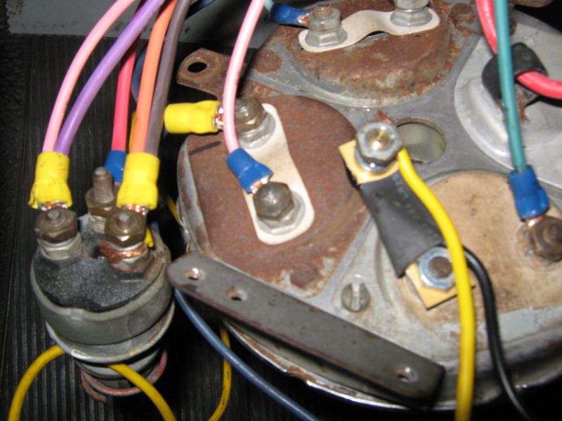
So, if you remove the independent voltage reducer from the back of the temp gauge completely, and hook up the dark blue wire (that is also running to power your fuel and oil pressure gauges - the third terminal of which is hanging loose in the upper pic) directly to the temp gauge (where the reducer used to be) it should work fine.
I remember seeing an independent yellow power wire going to the voltage reducer when it was installed as in the picture below (the first set you sent me). You can remove that yellow wire completely.
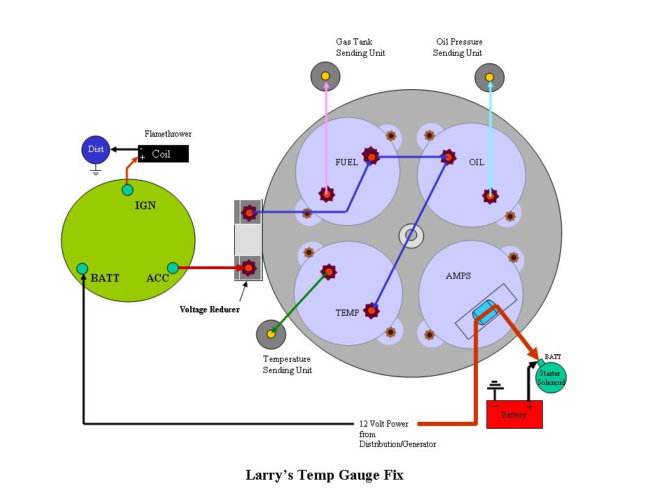
So when all is said and done your instrument panel should look like this. I think I have the wires colors correct, but the reducer is actually over between the AMPS and OIL PRESSURE gauges physically on the opposite side! But the wire flow is good as it is shown.
Make that fix then leave it with the mechanical gauge on one side and the electric on the other - hooked up as I told you before.
Take it out for another drive. I'll bet the electric temp gauge works fine now. Check it out, and let me know. If it still doesn't work then the sender's bad.
Pictures really help!
Larry, your gauge cluster already has a 12 volt to 6 volt reducer on it for all the gauges. That is that little cube on the cluster. See your last pic below:
I can't see it but I'm guessing that the darker blue wire that is running power to your gas and oil gauges is attached to the other end of that cube. The red wire is supplying 12 volt power into the cube from the ignition switch and the blue wire is 6 volt power out to the gauges.
So, now that you have changed your 12 volt TEMP sender to a 6 volt, that kills one of the two problems we had.
Not knowing the gauges were already getting reduced voltage, we added a voltage reducer to the temp gauge to correct it. So now it is being DOUBLE REDUCED (and thus doubling it's indication.
So, if you remove the independent voltage reducer from the back of the temp gauge completely, and hook up the dark blue wire (that is also running to power your fuel and oil pressure gauges - the third terminal of which is hanging loose in the upper pic) directly to the temp gauge (where the reducer used to be) it should work fine.
I remember seeing an independent yellow power wire going to the voltage reducer when it was installed as in the picture below (the first set you sent me). You can remove that yellow wire completely.
So when all is said and done your instrument panel should look like this. I think I have the wires colors correct, but the reducer is actually over between the AMPS and OIL PRESSURE gauges physically on the opposite side! But the wire flow is good as it is shown.
Make that fix then leave it with the mechanical gauge on one side and the electric on the other - hooked up as I told you before.
Take it out for another drive. I'll bet the electric temp gauge works fine now. Check it out, and let me know. If it still doesn't work then the sender's bad.
Pictures really help!
#17
06-23-2010, 04:08 PM

Join Date: Dec 2009
Location: Alvin, Texas 77511
Posts: 267
Likes: 0
Received 0 Likes
on
0 Posts
Julie in the pics of the gauges on the back the red wire that is hooked up to the little cube runs from the cube to the fuse box. So i am asuming that the red wire has 12 volts going through it to the cube. With the blue wire coming from the cube to all the gauges that is the way I have had it hooked up untill we put the separte reducer on the temp gauge. The truck was run as you asked in other threads and the temp gauge goes to cold than up to the H on hot. So we haven't really changed a thing in the wiring. Does it make any difference which side the little cube gets it's power from? The other wires that are hooked up on the other two gauges one goes to the oil sending unit and the other to the gas sending unit and they work along with the discharge gauge.
#18
06-23-2010, 05:57 PM
Post Fiend
Julie in the pics of the gauges on the back the red wire that is hooked up to the little cube runs from the cube to the fuse box. So i am asuming that the red wire has 12 volts going through it to the cube. Yes that's good - in my drawing I designated that 12 volt power to be coming from "12 Volt power - Generator/Distribution." A fuse block is "Distribution." With the blue wire coming from the cube to all the gauges that is the way I have had it hooked up untill we put the separte reducer on the temp gauge. That was wired correctly. When I asked if you had a reducer installed to make the 6 volt gauges work on your 12 volt system, I don't think you realized that that is what the little cube was. I didn't realize you already had a reducer back there when we went through the troubleshooting. Having the wrong sender will cause the same problem - so we are elliminating possibilities one by one. The truck was run as you asked in other threads and the temp gauge goes to cold than up to the H on hot. So we haven't really changed a thing in the wiring. Lets just try it with the small voltage reducer removed and the blue wire reinstalled. Does it make any difference which side the little cube gets it's power from? If your oil pressure and gas gauges are working then it is wired correctly. The temp should work correctly as well. The other wires that are hooked up on the other two gauges one goes to the oil sending unit and the other to the gas sending unit and they work along with the discharge gauge.
Mechanical gauge on one side and single post electrical sender on the other. The electrical temp gauge should indicate about a needle width higher than half way at 180 degrees. Make a note when you drive it what temp the mechanical gauge shows when the electric gauge hits the center mark.
As I mentioned then only thing left after that is that the sender is bad.
#20
06-23-2010, 07:43 PM
Join Date: Dec 2009
Location: Alvin, Texas 77511
Posts: 267
Likes: 0
Received 0 Likes
on
0 Posts
#21
06-23-2010, 08:15 PM
Post Fiend
No no no........It's ok that way. We just need a source of 12 volt power to the little cube voltage reducer. It doesn't matter where it comes from. OEM it would come from the ignition switch - you have rewired so your configuration is a little different. No sweat.
Here, I've modified the drawing for you:
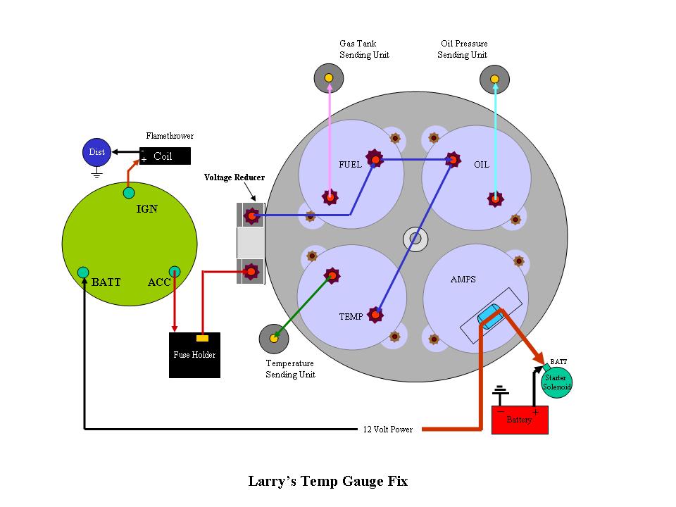
Just go ahead and remove the individual voltage reducer from the back of the temp gauge;
Remove the yellow power wire going to the individual reducer; and,
Hook the dark blue wire back up to the temp gauge.
Then drive and compare as described above.
Here, I've modified the drawing for you:
Just go ahead and remove the individual voltage reducer from the back of the temp gauge;
Remove the yellow power wire going to the individual reducer; and,
Hook the dark blue wire back up to the temp gauge.
Then drive and compare as described above.
#22
06-23-2010, 08:44 PM
Join Date: Dec 2009
Location: Alvin, Texas 77511
Posts: 267
Likes: 0
Received 0 Likes
on
0 Posts

#24
06-24-2010, 02:13 AM
Post Fiend
#25
06-24-2010, 02:19 AM
Post Fiend
Before you had (and didn't happen to mention) a Ford gauge voltage reducer (the little cube) supplying 6 volt power to two of the gauges with the third lead disconnected, and a separate 12 volt power source leading to an individual voltage reducer on the temp gauge. In theory that should have worked. Except you have rewired the truck and I have no idea how it was done or how you configurted it. And to be honest, I don't think you do either. Otherwise we would have known about the cube voltage reducer three threads and 45 posts ago.
And you haven't driven it since you took off the individual reducer, got rid of the yellow wire and hooked back up the blue wire. In other words you haven't test driven it since you changed it to how it is in the drawings. If it doesn't work this time, baring anything else bizar in the wiring, it HAS TO BE A BAD SENDER. There's nothing else left to correct.
All I did with the second drawing was incorporate your fuse holder to avoid further confusion about where your power comes from, and keep you from changing something that didn't need to be changed.
#26
06-24-2010, 03:55 PM
Join Date: Dec 2009
Location: Alvin, Texas 77511
Posts: 267
Likes: 0
Received 0 Likes
on
0 Posts
Ok Julie I traced all (I mean ALL) the wires on the truck and they are hooked up right according to what the wire says on them. I put the gauges and the starter switch back in the truck and took her for a drive to Alvin and back. When the electrical gauge pointed just a smig past the half way mark the mechanical gauge read around 173 to 178 somewhere in that range. The mechanical gauge doesn't have those marks on it so I am guessing a round number but it wasn't up to 180 yet. The electrical gauge didn't go to the hot H mark all the way there and back which is about 10 miles like it did before. This is with just water in radiator and driving 50 to 55 mph and the single sending unit in the left head. So what is next?
#27
06-24-2010, 06:18 PM
Elder User
Join Date: Oct 2003
Location: Canada
Posts: 785
Likes: 0
Received 0 Likes
on
0 Posts
I would just like to add a little to this confusion to the thermostat issue. I myself run 180s in my stock Flathead, and it runs along great.
Here is another one that maybe some of you may or may not agree with, but here it is.
I was talking with an elderly man from Nevada, he runs a stock 1937 Flathead, and he uses 180 Thermostats. He mentioned to me that he can run the Desert with no heating problems what so ever.
I was further talking to man up here in Canada, who runs a rad shop and he still does the "Rodding of Rads". He takes of the top tank and runs w wire brush down the tubes, cleaning them of the scale deposits. Now I asked him what degree Thermostats to run in my Flatty, he told me 180 Degree.
I took his advice and have run them ever since and that was about 5 years ago, also I do drill a small hole in the Thermostat.
I do flush my cooling system every 2 years and replace the Anti-Freeze.
On a fresh Engine I will add a pint of "Iron Tite" after I make sure there are no leakes. I add this to a warm engine through the Thermostat housings, so it goes directly into the engine. I help the coolant flow better, and will seal any minor cracks. "DO NOT ADD THIS DIRECTLY TO THE RAD", as you probably won't like the results.
You also as others have mentioned here, and I did also in another post, have the fan shroud, and the belly pan bottom underside of rad in place.
Your Rad has to do the cooling and it needs these items to be effiecient.
One other mention I see a lot of guys fill their Rads to the top of the Tank, this is inncorrect.
That why its called an expansion Tank, and it gives the coolant returning from the engine when the Thermostats to the Rad a place to go, instead of spewing it out through the over flow pipe. Finally the Rad Cap a low pressure cap is all that is required 3-4 lbs.
#28
06-24-2010, 07:27 PM
Post Fiend
Ok Julie I traced all (I mean ALL) the wires on the truck and they are hooked up right according to what the wire says on them. I put the gauges and the starter switch back in the truck and took her for a drive to Alvin and back. When the electrical gauge pointed just a smig past the half way mark the mechanical gauge read around 173 to 178 somewhere in that range. The mechanical gauge doesn't have those marks on it so I am guessing a round number but it wasn't up to 180 yet. The electrical gauge didn't go to the hot H mark all the way there and back which is about 10 miles like it did before. This is with just water in radiator and driving 50 to 55 mph and the single sending unit in the left head. So what is next?
So, the truck is running fine, maybe a smidge warm. But every little thing that is not finished will contribute about 3 to 5 degrees of warmer running. That doesn't sound like alot but when you add four things (no fan shroud, no lower pan, water not coolant, 6 volt coil [weaker spark will add 3 degrees just like the wrong spark plugs] it adds up - that's 9 to 12 degrees right there.
So, I'd put on your fan shroud and bottom pan, mix in a 50/50 mixture of coolant, put on the flamethrower when you get it, put in the 180 degree thermostats, and then drive it again. Check the temps on both gauges and if they haven't gotten worse, remove the mechanical gauge, install the electric overheat (two prong) sender in it's place, run the wire from the dash gauge to the two prong sensor then over to the one post sender, and you are good to go.
If you want to bring the temps down more, then the engine guys can have you do mechanical stuff like water pump impellers and such.
But your electric temp gauge is working properly now.

#29
06-24-2010, 08:06 PM
Join Date: Dec 2009
Location: Alvin, Texas 77511
Posts: 267
Likes: 0
Received 0 Likes
on
0 Posts
Ok Julie I have read your thread on the thermostats and I also drilled an 1/8" hole on each side of them as one guy recomended it is to let air out of the engine if there is an air pocket. I have been looking for a fan shroud to go on the radiator since you told me to get one and I finaly found one from Denny that he got off a 52 F1 in fact he had two that he wanted to sell. I bought one from him. I sent him the check yesterday so it should be here some time next week to install. He also has the belly pan and the over the radiator deflector for sell but I already have those on the truck. I guess my next step will be to take out the mechanical gauge and put in the double post temp sending unit back on. Hook it up and see if I get the same results on the electrical gauge as I did today. I know this doesn't make any since and probably had nothing to do with the results today but on the electrical gauge there where two nuts on each post so I took one off. That is the only change I did today and got better results. I know you think I'm farting in the wind saying that.
If I hook up the double sending unit and things go wrong again it has to be a bad sending unit on the double post one. Right? I still have not received my flame thrower epoxcy 12 volt coil yet so I called the company to see where it was and they had no record of the order so I went to another company on the internet and have one coming this time. The first one was ordered Jun 16th as you suggested me to get and install a while back.
Thanks for all the trouble you have gone through with this issue. I think your the best and wanted to say THANK YOU!
Larry Brauer
braular@yahoo.com
713-410-7481
#30
06-24-2010, 09:40 PM
I called my old cousin back and he told me that the temp guage does react to the 2 post switch, it moves to hot at around 200 to 210 degrees when the bi metal opens the curcuit in the switch. so i guess it doesnt Read but one , but the temp guage reacts to the curcuit opening causing it to go to hot. I think that bi metal opens the curcuit at a designed water temp, due to the fact that they are designed to be used in conjunction with matching radiator cap presures. i have not built one yet but i am going to build a flathead one day, prettest engine ever made.

