Need some ideas for my shock problem!!
#16
 05-19-2010, 05:28 PM


Join Date: May 2003
Location: Burlington, CT
Posts: 1,425
Likes: 0
Received 0 Likes
on
0 Posts
Do explain more on this wishbone upper if you can. If you dont mind. Thanks!!!
#17
05-19-2010, 07:38 PM
here's another sketch:
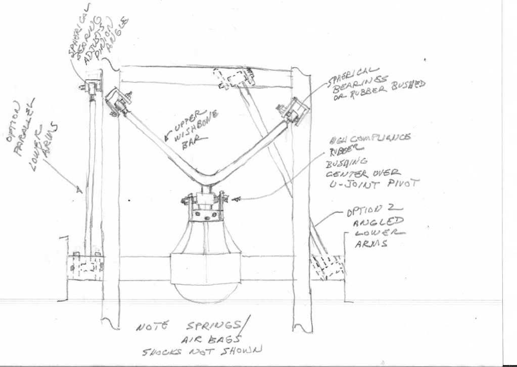
Note that sometimes the wishbone is reversed with the center at the crossmember and ends at the axle depending on clearance needs. The center of the V bar could be made so the center pivot was a seperate piece threaded thru it to give still another point of adjustment. The center bushing needs to be a high compliance type (large diameter with thick rubber to allow angular movement and road shock absorbtion. This type suspension has become somewhat the OEM norm (with the angled lower arms) so the parts are readily available at salvage yard.
Note that sometimes the wishbone is reversed with the center at the crossmember and ends at the axle depending on clearance needs. The center of the V bar could be made so the center pivot was a seperate piece threaded thru it to give still another point of adjustment. The center bushing needs to be a high compliance type (large diameter with thick rubber to allow angular movement and road shock absorbtion. This type suspension has become somewhat the OEM norm (with the angled lower arms) so the parts are readily available at salvage yard.
#18
05-20-2010, 04:25 PM

#19
05-20-2010, 07:20 PM
I was only trying to sketch the general layout. There is some good inexpensive suspension modeling software and reference books out there or you can build a scale model to play with pivot locations, arm lengths, angles to see what effect they have on the geometry, or you could do it the backyard engineer method, dummy and tack somepices together and move it around. I'd need a lot more info on the actual setup to even start giving measurements and that's more time and work than I have interest in investing in it right now. How much fun would it be if I gave all the answers? 
Typically the arms are different lengths and angles from each other. Bind shouldn't be a real issue if you use rubber bushed pivots and limit the range of movement.
Personally if I was dead set on airbags I'd probably have gone with the KISS principle and used a NASCAR long trailing arm, panhard bar setup.

Thread
Thread Starter
Forum
Replies
Last Post
rtcalabrojr
1948 - 1956 F1, F100 & Larger F-Series Trucks
10
12-20-2011 12:29 PM
rtcalabrojr
1948 - 1956 F1, F100 & Larger F-Series Trucks
13
08-22-2011 04:53 PM
rtcalabrojr
1948 - 1956 F1, F100 & Larger F-Series Trucks
8
05-15-2010 06:30 AM
rtcalabrojr
1948 - 1956 F1, F100 & Larger F-Series Trucks
26
11-03-2009 11:45 PM
rtcalabrojr
1948 - 1956 F1, F100 & Larger F-Series Trucks
18
09-02-2009 08:51 PM

