signal flasher question
#1
 04-05-2010, 08:19 AM


Join Date: Jun 2003
Location: Kannapolis NC
Posts: 285
Likes: 0
Received 0 Likes
on
0 Posts
#2
04-05-2010, 10:56 AM

#3
04-05-2010, 11:54 AM


#4
04-05-2010, 12:00 PM

#5
04-05-2010, 12:19 PM
Bob, bob, bob!
Yep I agree, it makes a lot of sense to NOT have the turn signal working on the front when the back ones burnt out, so that other drivers at intersections can not tell if you are turning left. Actually why have them all, we should just stick our arm out the window and point?
flasher.jpg
Yep I agree, it makes a lot of sense to NOT have the turn signal working on the front when the back ones burnt out, so that other drivers at intersections can not tell if you are turning left. Actually why have them all, we should just stick our arm out the window and point?
flasher.jpg
Last edited by Old F1; 04-05-2010 at 12:26 PM. Reason: add picture
#7
04-05-2010, 12:48 PM

Post Fiend
Ah it must be spring...all the tail light and signal light allergies are running rampant.
As far as the circuit and wiring signal flow are concerned, you have three different circuits that work your signal lights, the running (back tail) lights and parking (front marker) lights.
Power for your running and parking lights is powered off the headlight switch - each has it's own post and they function differently - the parking lights go out when the main headlights are turned on and the tail lights remain on.
You signal lights are powered in the front via their own circuit that flows up from the flasher through the signal switch, and out to the front marker lights.
The back signal lights utilize the brake lights in order to work. Power for them flows through the brake light switch (on the back of your master cylinder) then up to the signal switch.
If the signal switch is not activated then power flows out of the signal switch back to the brake lights on both sides (notice I did not say it flows through the flasher).
If the signal switch is activated, then power to the rear light not selected to flash is still provided by the brake light circuit lighting the brake light on the non selected side. The side that is selected to flash recieves power from a separate source, goes through the flasher, up to the signal switch and out to the light selected to flash.
The power source for the Parking lights and Running lights using the headlight switch is HOT (I call that "HOT BUS" in my drawing). Meaning it is powered even when the key is not on.
Likewise, the Brake light circuit is HOT all the time.
The signal light flasher is on a SWITCHED circuit (I call that "SWITCHED BUS" on my drawing) which means it is powered only when the ingnition switch is turned on.
The mechanical workings of the switch are not so important, but there is a diagram (that I can't seem to locate at the moment) that shows the contact points in the three different selected positions. Maybe someone else can post it - it's fairly common.
Also fairly frequent lately is my light wiring diagram which is the picture equivelant of what I described above. It tends to make life easy when it comes to understanding the wiring and signal flow. Here it is:
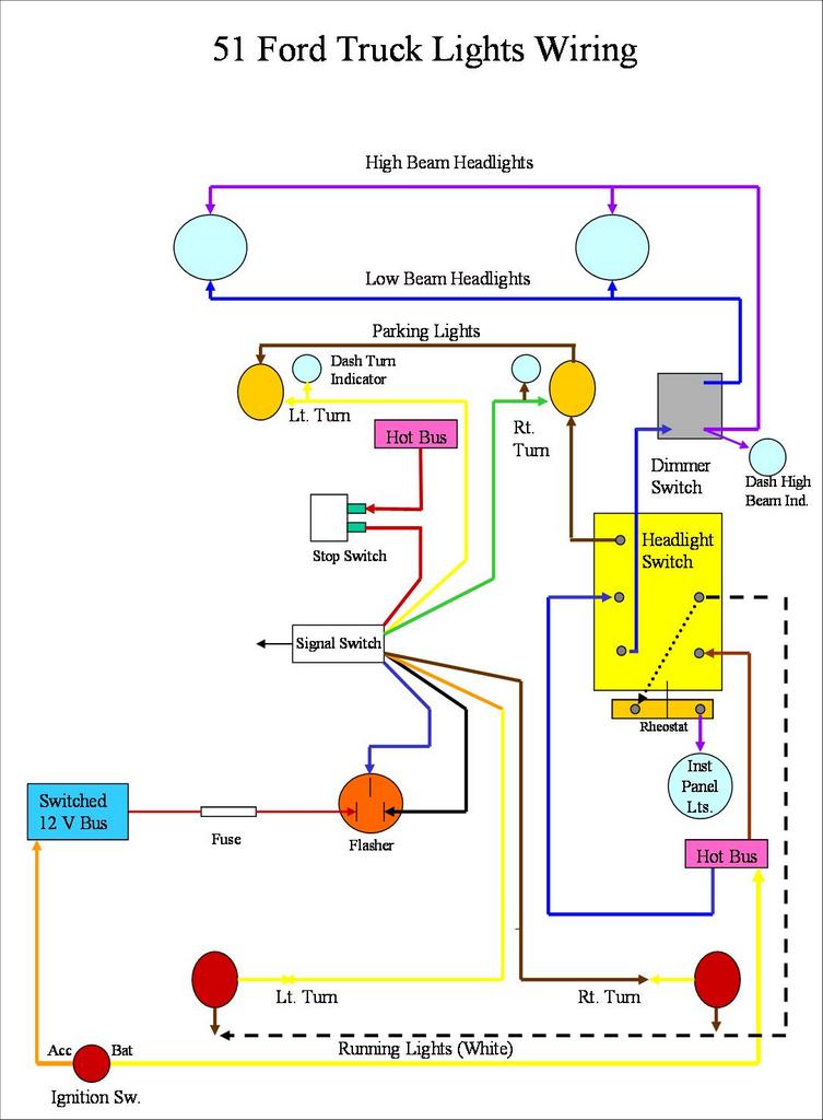
Hope that helped. If you have any more questions, feel free to ask!
As far as the circuit and wiring signal flow are concerned, you have three different circuits that work your signal lights, the running (back tail) lights and parking (front marker) lights.
Power for your running and parking lights is powered off the headlight switch - each has it's own post and they function differently - the parking lights go out when the main headlights are turned on and the tail lights remain on.
You signal lights are powered in the front via their own circuit that flows up from the flasher through the signal switch, and out to the front marker lights.
The back signal lights utilize the brake lights in order to work. Power for them flows through the brake light switch (on the back of your master cylinder) then up to the signal switch.
If the signal switch is not activated then power flows out of the signal switch back to the brake lights on both sides (notice I did not say it flows through the flasher).
If the signal switch is activated, then power to the rear light not selected to flash is still provided by the brake light circuit lighting the brake light on the non selected side. The side that is selected to flash recieves power from a separate source, goes through the flasher, up to the signal switch and out to the light selected to flash.
The power source for the Parking lights and Running lights using the headlight switch is HOT (I call that "HOT BUS" in my drawing). Meaning it is powered even when the key is not on.
Likewise, the Brake light circuit is HOT all the time.
The signal light flasher is on a SWITCHED circuit (I call that "SWITCHED BUS" on my drawing) which means it is powered only when the ingnition switch is turned on.
The mechanical workings of the switch are not so important, but there is a diagram (that I can't seem to locate at the moment) that shows the contact points in the three different selected positions. Maybe someone else can post it - it's fairly common.
Also fairly frequent lately is my light wiring diagram which is the picture equivelant of what I described above. It tends to make life easy when it comes to understanding the wiring and signal flow. Here it is:
Hope that helped. If you have any more questions, feel free to ask!
Trending Topics
#8
04-06-2010, 08:59 AM
Join Date: Jun 2003
Location: Kannapolis NC
Posts: 285
Likes: 0
Received 0 Likes
on
0 Posts
All good answers now let me tell my problem to see if anyone has a suggestion. The park lights work , the brake lights work , the hazard lights all flash. But the turn signals do nothing , not on, not flashing, nada. I have check the flasher and exchanged it for the hazard flasher with no change. the hazard flasher has power coming to it through one of the two terminals but the turn signal flasher does not have any power to it on either terminal in any condition, lighs on/off switch on / off. BTW it is an EZ2 wire system with the 21 circuits. The flashers are mounted directly to the fuse panel itself so unless power is supplied to it from somewhere else I assumed the fuse box itself may be faulty. Would that be a good assumption?. If the power is supplied form somewhere else where would that be. Thanks in advance
#9
04-06-2010, 09:06 AM
Post Fiend
Well first remember, you have to have the key on for the signals to work (or at least you should). All the other items you mentioned are hot.
If the brake lights work and the parking lights work, then either your signal switch is bad or it is wired incorrectly - probably at the switch.
What type of switch are you using?
If the brake lights work and the parking lights work, then either your signal switch is bad or it is wired incorrectly - probably at the switch.
What type of switch are you using?
#10
04-06-2010, 10:32 AM
the hazard flasher has power coming to it through one of the two terminals but the turn signal flasher does not have any power to it on either terminal in any condition, lighs on/off switch on / off. BTW it is an EZ2 wire system with the 21 circuits. The flashers are mounted directly to the fuse panel itself so unless power is supplied to it from somewhere else I assumed the fuse box itself may be faulty.
you should be able to read/measure 12 volts at one of the two contacts that the flasher unit hooks to...... so as you said internal failure of the bus that supplies power to the flasher unit, new box unlikely but still possible.... blown fuse maybe.. I believe that the flasher and the horn share the same fuse.. so you see the test here don't you If the fuse is blown the fuse panel may be good..... you may have a turn signal wire shorted to ground and as soon as the turn signal is selected the fuse blows... it would have to be before the turn signal switch though, since the brake lights work and apparently do not blow fuses, and the brakes use the same wiring from the turn signal switch back to the lights...... my wild *** guess for the day
#11
04-06-2010, 08:23 PM
Post Fiend
#12
04-09-2010, 02:32 PM
Join Date: Jun 2003
Location: Kannapolis NC
Posts: 285
Likes: 0
Received 0 Likes
on
0 Posts
Just to update the progress on this problem, and I do thank all who helped. I checked all the fuses and none were blown and I check for power to the flasher(for the signal lights ) with the switch on and off--no power So I swapped the two wires going to the column one was the flasher power and one was the turn signal power, now I have turn signals which work with the ign. switch on or off but now I have no flashers . This does not seem to be much of a problem unless someone can point out a problem which I have not seen. The other thing is there is no horn now so I guess I will have to find a source of non switched power to tap into to power the horn. I now looks like the fuse box itself was / is at fault even though it is new. Any other thoughts? Thanks

#14
04-10-2010, 12:46 AM
Post Fiend
Remember, power comes into the signal circuits from TWO different places. Power to the brake light switch then up to the signal switch,
AND there is a seperate power input to the flasher! Power does not come down from the column on either, it is supplied from your power distribution source (fuse block) directly to those two items then goes up to the signal switch.
Check out the picture I posted. Busses are Fuse Blocks in that diagram. (being a pilot you know what busses are, right?)
#15
04-10-2010, 08:50 AM
Join Date: Jun 2003
Location: Kannapolis NC
Posts: 285
Likes: 0
Received 0 Likes
on
0 Posts