No spark
#31
 03-07-2010, 07:14 PM

Elder User
Join Date: May 2006
Location: Kansas City, Mo
Posts: 907
Likes: 0
Received 0 Likes
on
0 Posts
On the first picture the wire from the capacitor looks like it has been pinched/cut. On the last pictures the wire looks like it laps over the edge of the metal housing. When you push it back in the housing to install the cap maybe the wire touches the housing and shorts out. You were getting close and then replaced several parts. When you do this you bring the possability of more bad or incorrectly installed parts. chuck
#32
03-07-2010, 07:27 PM
49, no the wire from the cap isnt cut or pinched. I tried to see if i could get spark from the points with the cap of and the ground wire didnt look like it was touching anything but i will double check and make sure it isnt. I seen at another forum about inline 6 ford engines that the gap is suppose to be set at .25 so ill give that a shot to. Who knows tomorrow i should get the new distributor i ordered last week and if this fails tonight ill pop that in and see what happens i guess. 
#33
03-07-2010, 08:07 PM
Elder User
Join Date: Sep 2009
Location: Indiana
Posts: 693
Likes: 0
Received 0 Likes
on
0 Posts
49, no the wire from the cap isnt cut or pinched. I tried to see if i could get spark from the points with the cap of and the ground wire didnt look like it was touching anything but i will double check and make sure it isnt. I seen at another forum about inline 6 ford engines that the gap is suppose to be set at .25 so ill give that a shot to. Who knows tomorrow i should get the new distributor i ordered last week and if this fails tonight ill pop that in and see what happens i guess.
#34
03-07-2010, 08:48 PM
 YAY, finally she fired up. The problem was when i tightened the wires up comming from the coil had been touching the body of the distributor so it was grounding out. tomorrow i will replace the fuel pump with a new one and see if she will suck gas out of a gas can so it will run longer that the 3 seconds from the shot of either....
#35
03-07-2010, 08:57 PM

good job. I would be very careful replacing parts in the future when you have a issue.
In most cases you can get what you have working enough to get it running. Then when you replace something and have issues you can narrow it down to the new parts.These old truck are fairly simple if you just work through your problems one step at a time and don't get frustrated and start replacing parts, having no idea whats wrong.
Congrats on getting it running
Larry
#36
03-07-2010, 09:55 PM

What a mess, the wire to the coil is supposed to go through the white thing but hang on for now; I have sent a PM Julie who has a wiring diagram for you.
Are you sure that the white # 1 wire is from the ignition switch? If the power from the ignition switch does not go through the white thing (ballast resistor) your points will burn in no time. Also there is a small wire from the S terminal on the starter solenoid that also goes to the coil bypassing the white thing to give 12 volts when starting.
Are you sure that the white # 1 wire is from the ignition switch? If the power from the ignition switch does not go through the white thing (ballast resistor) your points will burn in no time. Also there is a small wire from the S terminal on the starter solenoid that also goes to the coil bypassing the white thing to give 12 volts when starting.
Last edited by Old F1; 03-08-2010 at 05:19 PM. Reason: not "S" it should be "I" My senior moments are getting longer!
#37
03-07-2010, 10:57 PM
#38
03-07-2010, 11:05 PM

Post Fiend
Well, congratulations on getting the old girl running! I might be tempted to go buy a Lottory ticket - your pretty lucky!
I looked at your pictures and Old is understating a little - that wiring is a disaster. I tend to be a perfectionist - spend the $200 and get the EZ wire.
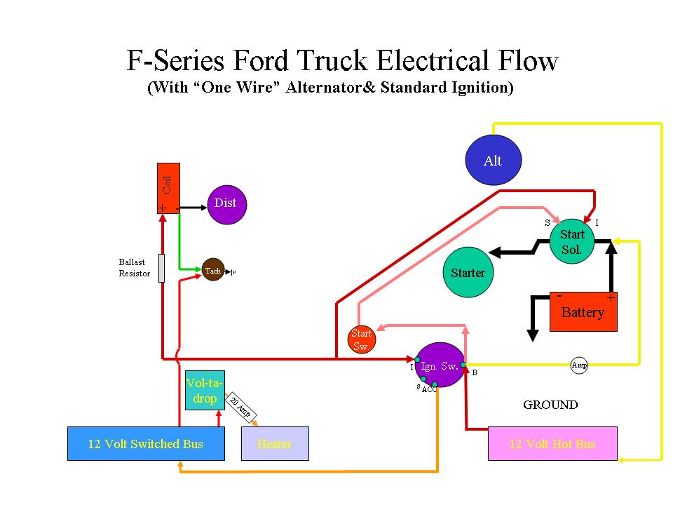
The signal flow on the ignition wiring is very simple: Power flows from the "Ign" terminal of the ignition switch to one terminal of the "White Thing" which is a ceramic block holding a "Ballast Resistor."
So, in from the ignition switch to the ballast resistor, then out from the OTHER terminal on the resistor to the positive post on the coil. The negative post of the coil runs to the distributor and the points. As you discovered, nothing can be chaffed or bare to ground out.
Now there is one more wire on a 12 volt conversion. It runs from the "I" terminal on the Starter Solenoid and is tapped into the wire running from the ignition swith to the ballast resister - before it gets to the resistor. You can do that one of three ways: you can run it directly to the "Ign" post on the ignition switch; you can run it directly to the post of the Ballast Resistor that is connected to the "Ign" post of the ignition switch; or, you can slice it into that wire anywhere between the two (ignition switch and ballast resistor). See the diagram below. Note that it is for a one wire alternator - which I don't think you have. But it's not related. The ignition circuit and starter button flow is seperate and that is what yours should look like. Busses are the places you are distributing power out of - like a fuse block. Hot is on all the time (lights, brake lights, etc). Switched is turned on with the key (heater, radio, etc). I'm not going to guess at how that mess is powered or distributed. After awhile, it should all be replaced, and we can help you with that.
I noticed that your primary ignition power wire goes into the ballast resistor then out from the same post, that's wrong, and I don't know what you have connected to the other side of the ballast resistor???????
Anyway, if you ever need wiring diagrams, you can check out my #4 gallery - there's lots there. Or if you ever have any questions, just send me an e-mail - I'll be glad to help.
I looked at your pictures and Old is understating a little - that wiring is a disaster. I tend to be a perfectionist - spend the $200 and get the EZ wire.
The signal flow on the ignition wiring is very simple: Power flows from the "Ign" terminal of the ignition switch to one terminal of the "White Thing" which is a ceramic block holding a "Ballast Resistor."
So, in from the ignition switch to the ballast resistor, then out from the OTHER terminal on the resistor to the positive post on the coil. The negative post of the coil runs to the distributor and the points. As you discovered, nothing can be chaffed or bare to ground out.
Now there is one more wire on a 12 volt conversion. It runs from the "I" terminal on the Starter Solenoid and is tapped into the wire running from the ignition swith to the ballast resister - before it gets to the resistor. You can do that one of three ways: you can run it directly to the "Ign" post on the ignition switch; you can run it directly to the post of the Ballast Resistor that is connected to the "Ign" post of the ignition switch; or, you can slice it into that wire anywhere between the two (ignition switch and ballast resistor). See the diagram below. Note that it is for a one wire alternator - which I don't think you have. But it's not related. The ignition circuit and starter button flow is seperate and that is what yours should look like. Busses are the places you are distributing power out of - like a fuse block. Hot is on all the time (lights, brake lights, etc). Switched is turned on with the key (heater, radio, etc). I'm not going to guess at how that mess is powered or distributed. After awhile, it should all be replaced, and we can help you with that.
I noticed that your primary ignition power wire goes into the ballast resistor then out from the same post, that's wrong, and I don't know what you have connected to the other side of the ballast resistor???????
Anyway, if you ever need wiring diagrams, you can check out my #4 gallery - there's lots there. Or if you ever have any questions, just send me an e-mail - I'll be glad to help.
#39
03-07-2010, 11:57 PM

Senior User
Join Date: Aug 2002
Location: east of DFW
Posts: 449
Likes: 0
Received 0 Likes
on
0 Posts
#40
03-08-2010, 01:53 AM
Post Fiend
But, I'll check just to be sure.
#41
03-08-2010, 10:15 AM
Julie
I think the wire from the I post on the sol. goes directly to the coil. That supply's full voltage only during the start cycle. When the sol. retracts then coil voltage returns through the resister lowering voltage to prevent point burn up.At least thats the way 6 volts work and no reason 12 would be different. It simply bypasses the resister to provide full voltage for easier starts.
But then I am old and mostly senile and could be wrong.
Larry
#42
03-08-2010, 11:17 AM
Post Fiend
Julie
I think the wire from the I post on the sol. goes directly to the coil. That supply's full voltage only during the start cycle. When the sol. retracts then coil voltage returns through the resister lowering voltage to prevent point burn up.At least thats the way 6 volts work and no reason 12 would be different. It simply bypasses the resister to provide full voltage for easier starts.
But then I am old and mostly senile and could be wrong.
Larry
I think the wire from the I post on the sol. goes directly to the coil. That supply's full voltage only during the start cycle. When the sol. retracts then coil voltage returns through the resister lowering voltage to prevent point burn up.At least thats the way 6 volts work and no reason 12 would be different. It simply bypasses the resister to provide full voltage for easier starts.
But then I am old and mostly senile and could be wrong.
Larry
Actually, I heard somewhere here it could be done either way. All you are looking for is the boost from the solenoid. It's still going to work even if it gets reduced down.
#43
03-08-2010, 12:17 PM
Julie
You may well be correct on the wiring. On the old ford cars, there is a resister under the dash on the firewall. It reduces the voltage going to the coil from 6 to 3 volts. It was very common to go from the starter side of the sol. to the coil with a wire, bypassing the resister. That way when the starter button was pushed it gave full 6 volts to the coil.
Looks like you have a lovely place to live from your trailer pictures. Sure beats N. Missouri this time of year.
Larry
#44
03-08-2010, 12:50 PM
Post Fiend
#45
03-08-2010, 10:06 PM
Elder User
Join Date: May 2006
Location: Kansas City, Mo
Posts: 907
Likes: 0
Received 0 Likes
on
0 Posts

