
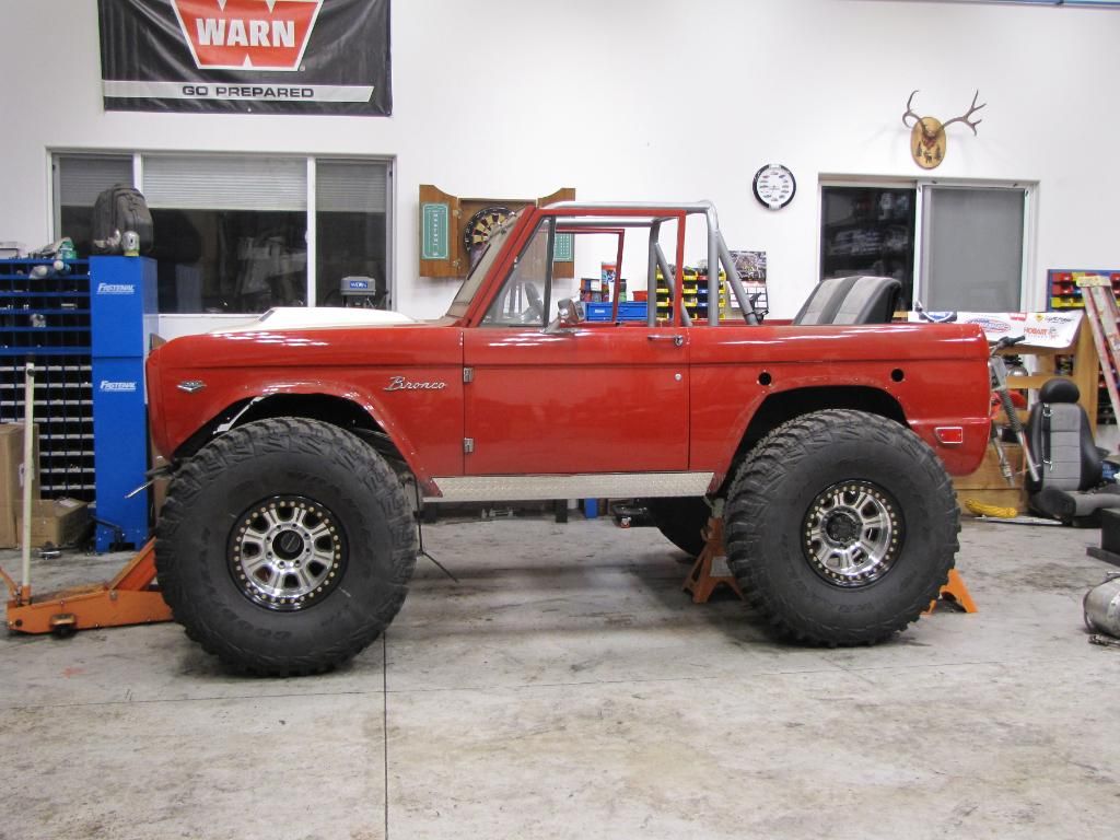
Red Label 68 Bronco 4.6 4V and 42" MTRs
#1
 12-25-2009, 03:01 AM

Red Label 68 Bronco 4.6 4V and 42" MTRs
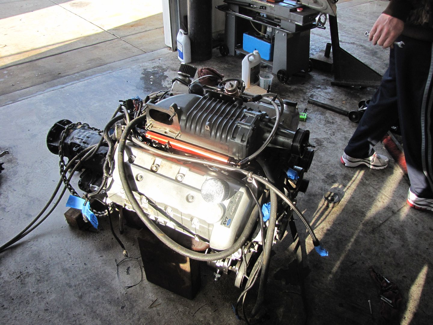
New start, new thread, new name. Same plan just bit off more than I can chew right now. 4V accessory setup is retarded. Using a 2V or 3V would be a snap compared to this. As far as the motor I have to have some custom mounting for the alternator and do some frame notching still to clear my steering. Oh well it's the way things go when your re inventing the wheel. At least looking at things with the rear under it it all is starting to make since. Now it's just some cutting and fabing for the motor and t case then just connecting the dots. Oh and custom up headers to clear the frame.
1968 Ford Bronco
2003 4.6 SVT Motor
Art Carr C6
Stak 3 Speed T Case
2004 SuperDuty Front and Rear Axles
42" GTR Kevlars
17" Raceline Monster Beadlocks
Detroit Rear
E Locker Front
3 Link Front
4 Link Rear
Coilover Front
Hybrid Nitro Rear
YouTube - Red Label Build Compelation Update


1968 Ford Bronco
2003 4.6 SVT Motor
Art Carr C6
Stak 3 Speed T Case
2004 SuperDuty Front and Rear Axles
42" GTR Kevlars
17" Raceline Monster Beadlocks
Detroit Rear
E Locker Front
3 Link Front
4 Link Rear
Coilover Front
Hybrid Nitro Rear
YouTube - Red Label Build Compelation Update
#2
12-25-2009, 03:28 AM

That's gonna be one helluva build. Be interesting to watch it develop and then get out on the road ... um.... so to speak.
Gotta sit higher with those monster meats rolling it along. Unless, of course, there isn't much "give" designed into the suspension.
I do like your choice for a powerpant though. Ufdah!
Gotta sit higher with those monster meats rolling it along. Unless, of course, there isn't much "give" designed into the suspension.
I do like your choice for a powerpant though. Ufdah!
#3
12-25-2009, 10:43 AM
Posting Guru
Join Date: Aug 2009
Location: Union Lake MI
Posts: 2,165
Likes: 0
Received 0 Likes
on
0 Posts
#4
12-31-2009, 10:23 PM
More Turbo
#5
12-31-2009, 11:32 PM
#6
01-01-2010, 01:46 AM
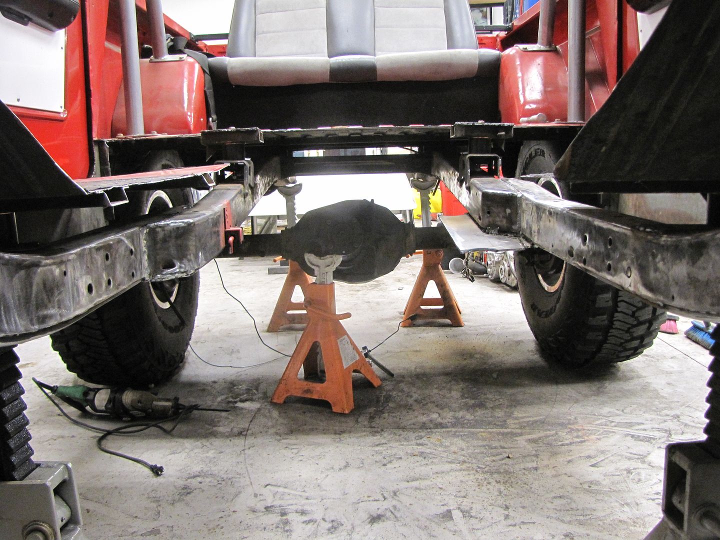
New 12/31/09
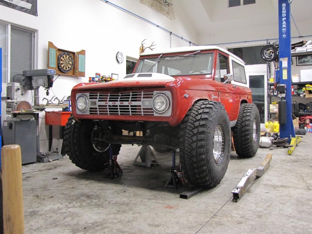
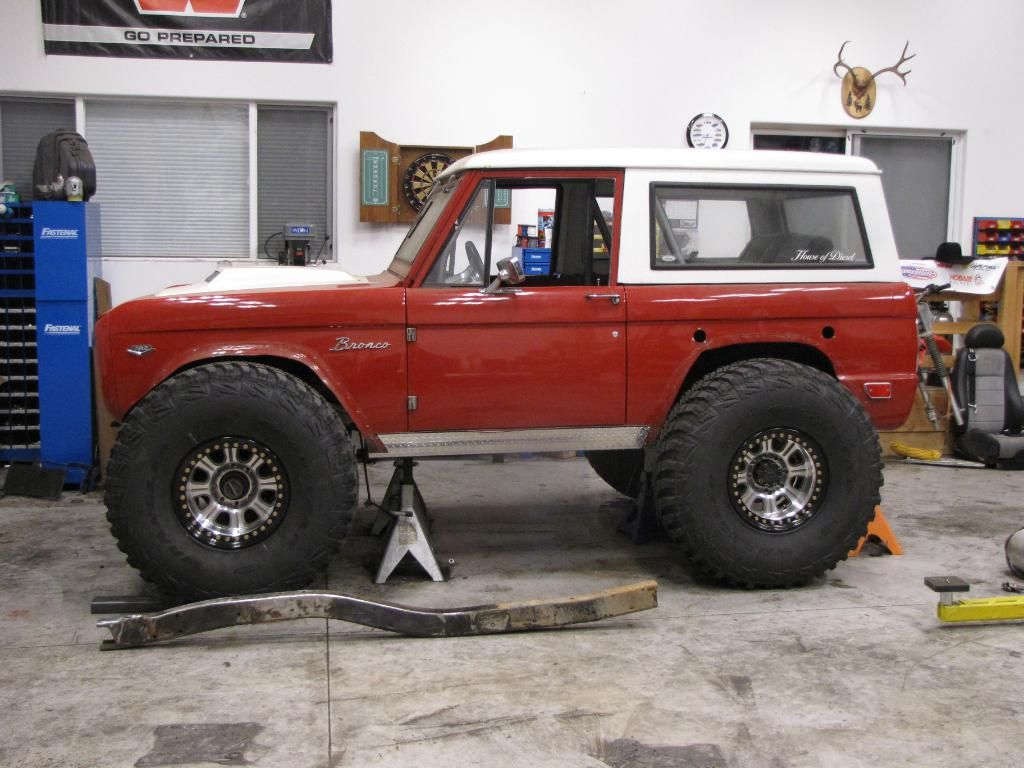
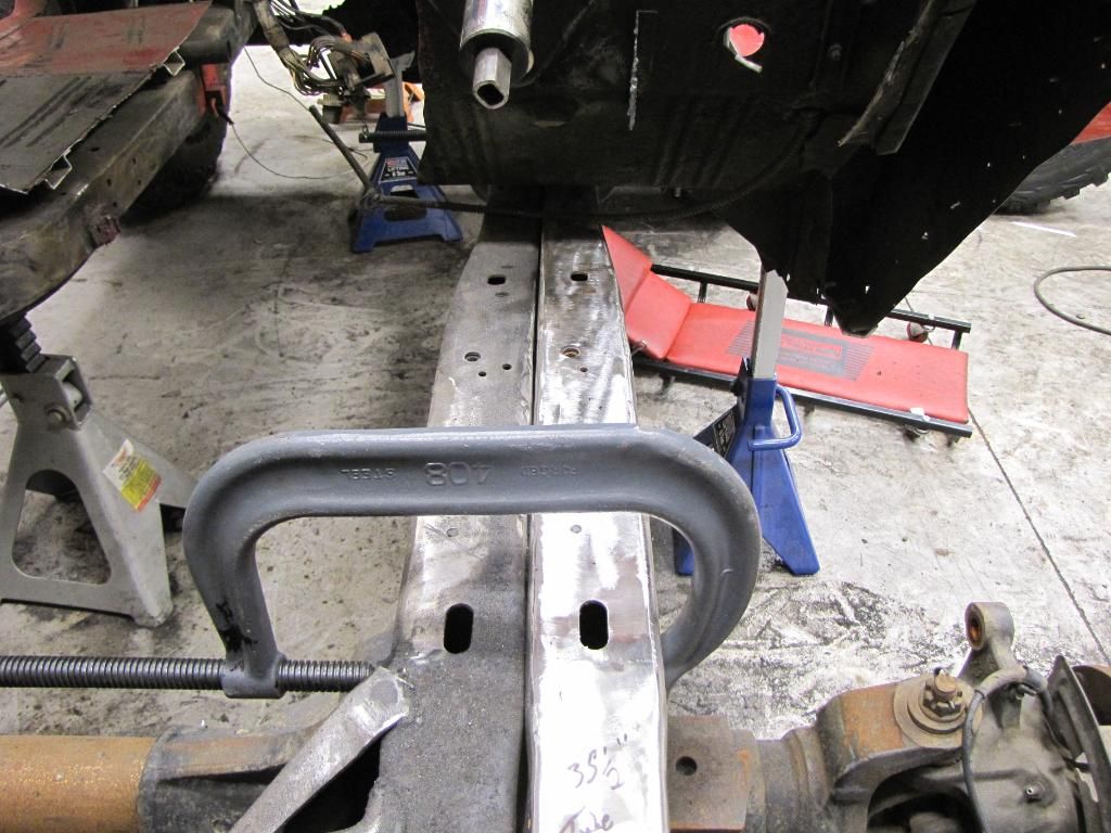
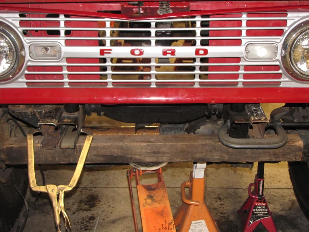
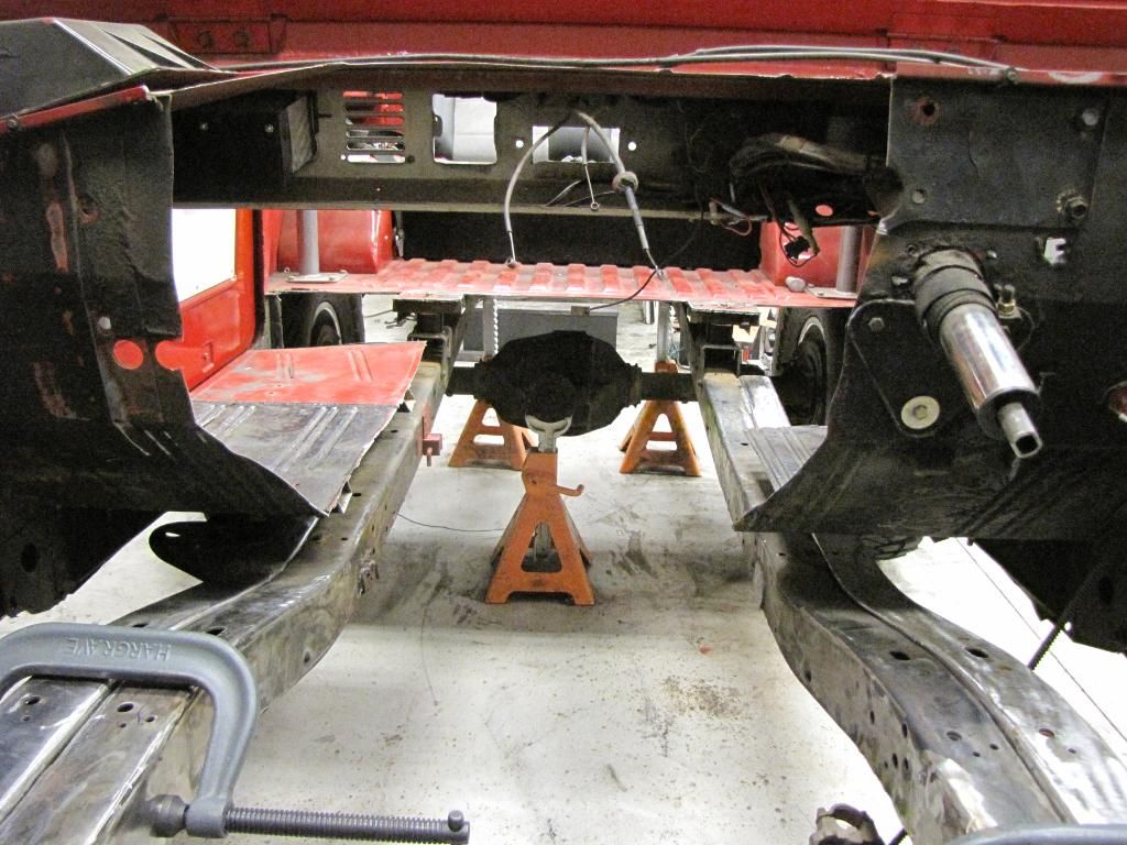
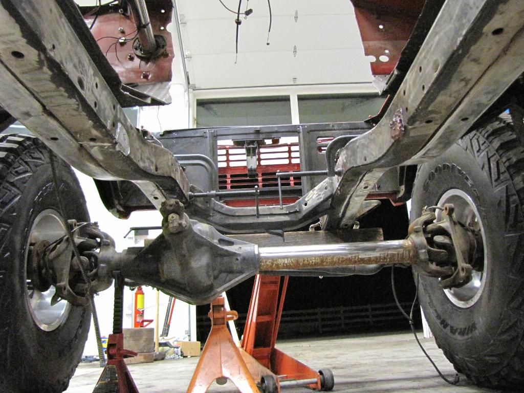
Ok, so I threw the front axle under to see how it looked and how much body would have to be cut. The Front output shaft is right in the middle of the frame rail. After thinking about how much more work it'd be I realized it'll be easier just to step the driver side frame rail out. While trying to figure out whether to use the frame I have or buy a new driver side rail to get good overlap, I realized I had a rusted body and frame in the back yard for another build that I wasn't going to use the frame for anyways. So rather than blocking the frame in two separate areas, one for the Stack T-case and another for the steering/alternator overlap, I'll simply offset the driver side frame rail from just in front of the drivers body mount all the way to the front. This will basically create enough room for everything. Oh and the front is going to come up about 1" to 2"s.
#7
01-01-2010, 02:54 AM
Trending Topics
#8
01-03-2010, 10:23 PM
Postmaster
#9
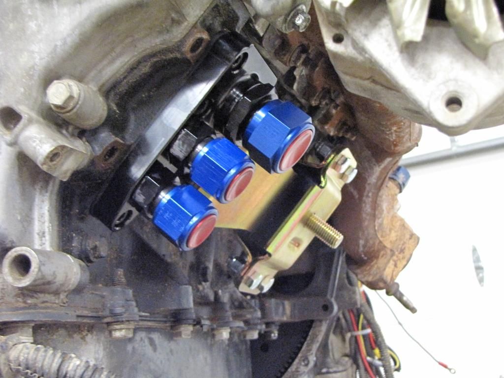
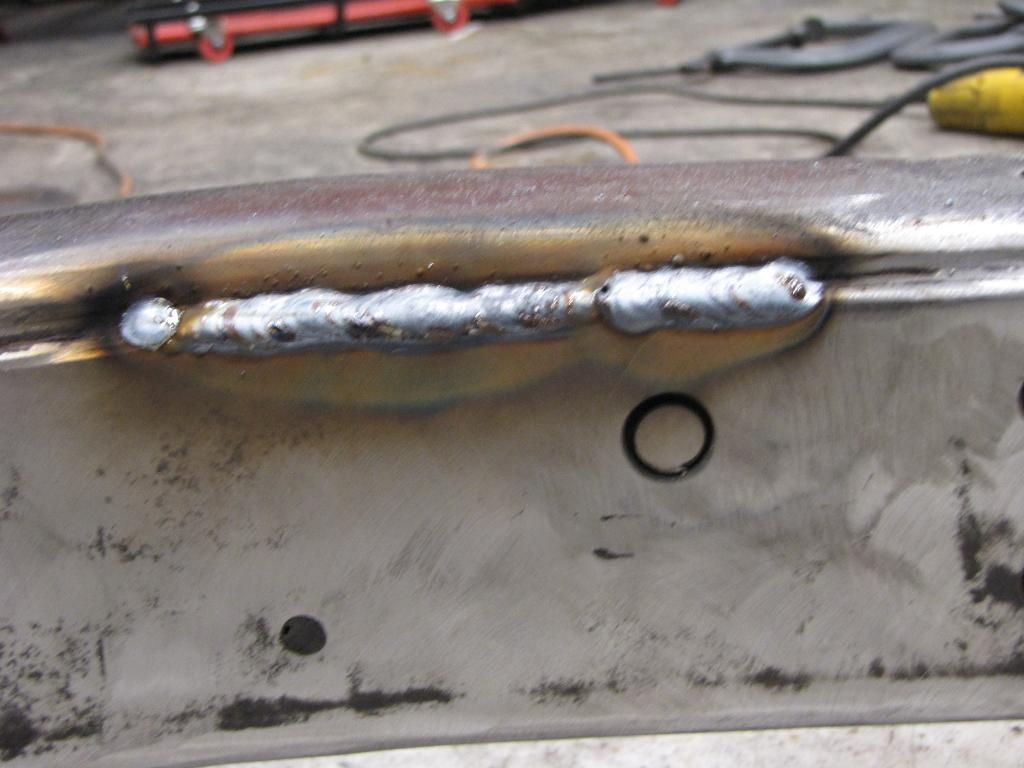
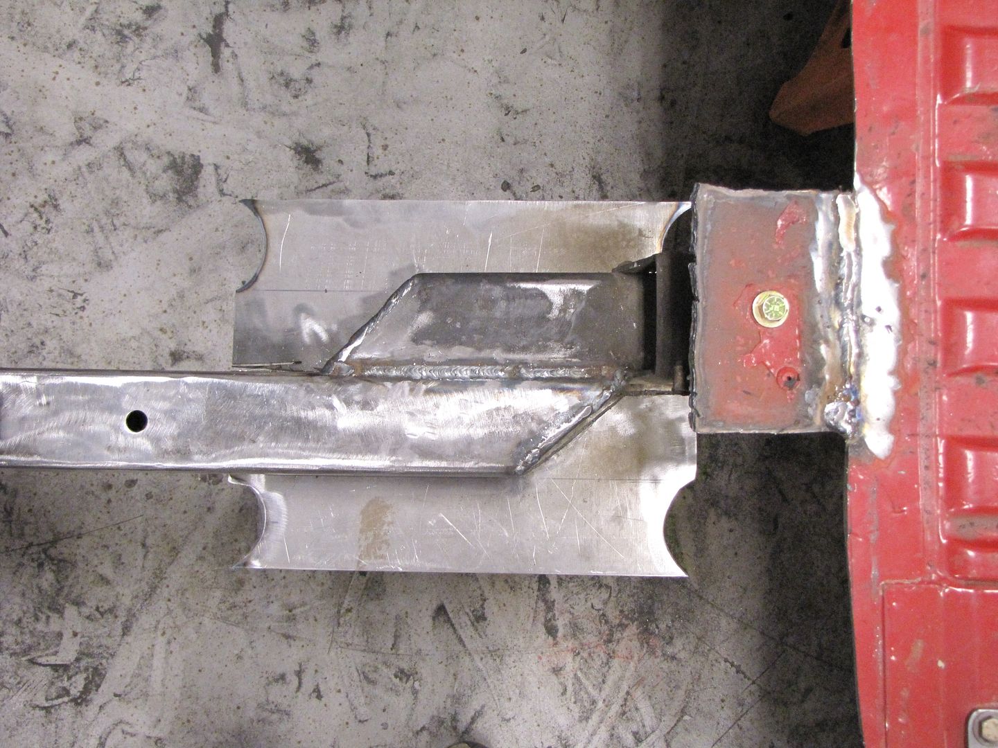
01-04-2010, 02:34 AM
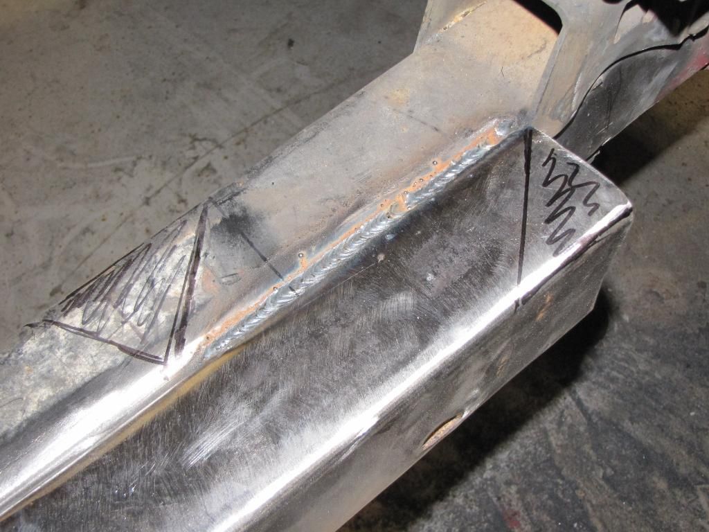
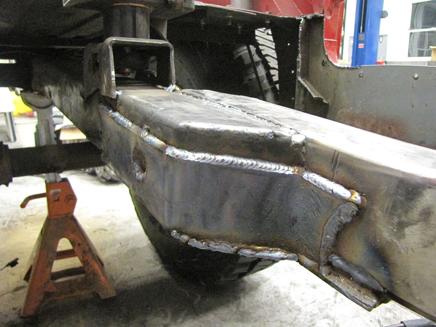
Well lets see, it was a productive weekend. Threw on the new motor mounts, remote oil filter setup, and got the frame in and laid out. I noticed some gaps in the slipped frame rail while I was prepping the it so I filled them while it was out. I'm a novice welder so go easy on me. lol Plan is to saddle it from the bottom and up both side, and then plate the top and the joints. For the passenger side I'm only going to run the frame rail about a foot into the cab to stagger my joints and not have joints directly across from each other. Looks like it's going to lay things out nicely. I'll be able to get the motor a little lower and further back and have to do a lot less work. I'm going to make sure I take my time laying out the crossmembers and steering to try and avoid issues further along in the build. Moveing the frame rails out is making it tight for the coilover setup, but laying out the links, driveline, exhaust, and other stuff will be way easier. It's definitely worth the extra work. Only thing I'm pounding my head on is how to move the Power Steering box forward. I have it all the way tight to the inner grill support and body mount, and I probably need another 3" to 4"s for the pitman arm to line up right with the steering. I read an article tonight in 4 Wheel Drive though were they made the pitman arm like a boomerang to retain the full steering radius. I have to figure it out before I weld in and drill the new front crossmember. Oh well, the plan for the next week or so is to get the passenger frame rail in, get body mounts back on, order and install new fluid damper/crank pulley, layout new alternator mounting, and get everything back in to start laying out motor mount/crossmember, trans mount crossmember, and steering.
#10
01-04-2010, 01:20 PM
Posting Guru
Join Date: Aug 2009
Location: Union Lake MI
Posts: 2,165
Likes: 0
Received 0 Likes
on
0 Posts
#11
01-08-2010, 03:22 AM
UPDATE 1/7/10
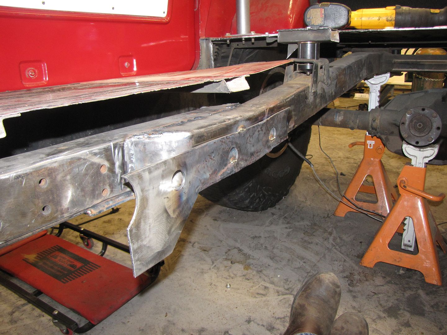
Ok, so while I was looking at body mounts on the Wild Horse sight and found saw the 1" body lift I decided to buy them to see if they might help me out a bit and create some breathing room. I hate body lifts and consider it totally cheating, but for setting up the three link, it allowing me to get more separation out of my links and mount the top link slightly above the frame. So we got the other frame rail tucked up and tacked. As for the front crossmember and steering setup I have to wait for the outer knuckles and high steer arms from Currie and the drag link and tie rod from Ballistic.
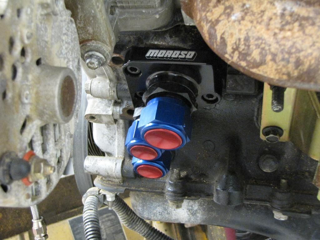
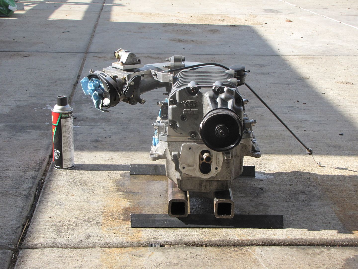
The other pics are of where we are tucking the alternator up and in to create more room for the steering on the driver rail. I am completely eliminating the lower bracket that the secondary main pulley and alternator mounted to. The main pulley is a weird 4 piece setup that uses a bearing in the center of the bracket to keep it spinning true. So I'm going to have a friend machine me a one piece aluminum one that will screw directly to the crank pulley. I have 10.7 pounds to work with so every ounce I save will be a bonus not to mention the lost drag. It's all working out kinda nice. Only other things to work out is moving and mounting one tension pulley and a lower bracket for the alternator.
Oh and if anyone wants the cage PM me. I'm going to make a hole new setup to tie in the body tubing and rear shock mounts. It's fully powder coated.
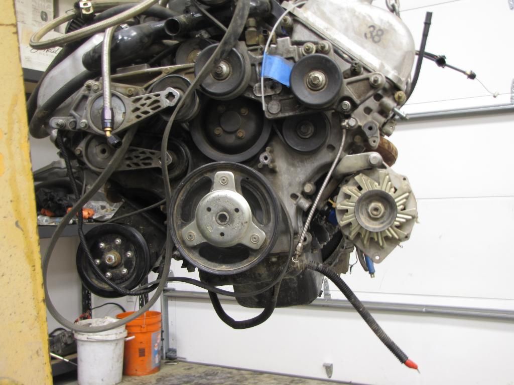
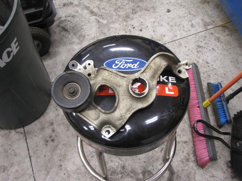
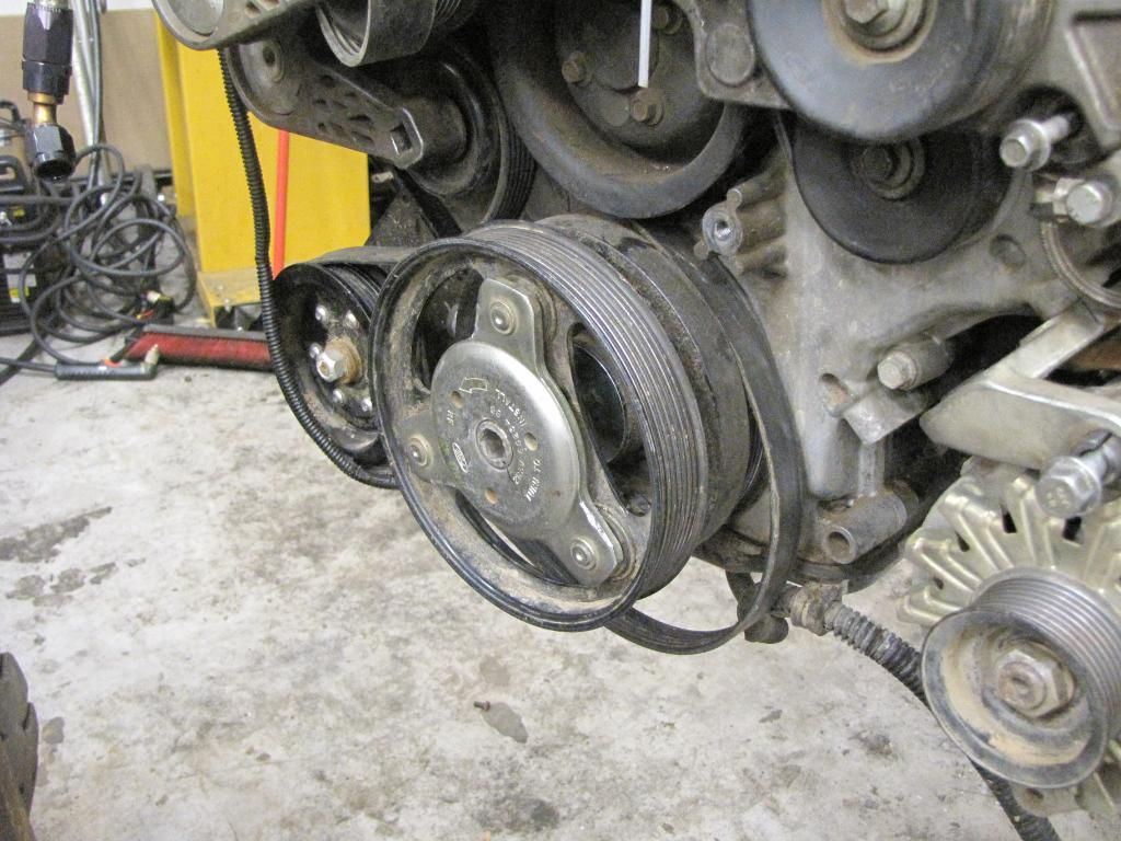
#13
01-11-2010, 04:54 PM
#14
01-12-2010, 01:31 PM
UPDATE 1/12/10
Well took the charger off and sent her out to Steg's to get ported and cut out the rear section to start welding in saddles while waiting for the outer knuckles and steering components. The front crossmember is going to tie into the Steering box plate so I have to wait for that stuff before I start drilling and cutting. Oh well there is plenty of plating to do in the new sections and the rest of the parts should be here tomorrow anyways.
The inside of the motor looks like things have been holding up just fine but for some reason all of the intake plenum bolts on the driver side rail were sheared and the passengers were bent. Luckily no damage on the inside though. Oh well here are some pics of the progress.
The inside of the motor looks like things have been holding up just fine but for some reason all of the intake plenum bolts on the driver side rail were sheared and the passengers were bent. Luckily no damage on the inside though. Oh well here are some pics of the progress.
#15
01-12-2010, 01:53 PM
Posting Guru
Join Date: Aug 2009
Location: Union Lake MI
Posts: 2,165
Likes: 0
Received 0 Likes
on
0 Posts