Steering Arm - What type is this?
#1
 10-22-2009, 07:45 PM


Steering Arm - What type is this?
Hi folks,
I am trying to install a No-Limit Straight Axle rack & pinion sterring kit.
As I examine what is on my 56 F-100, I am starting to wonder if it is the stock axle. The upright (?) looks a lot different than that shown in the instructions from No-Limit.
It looks like the steering arms provided by No-Limit will line up with holes in the upright (or is it a knuckle?). But it appears they will be spaced farther outwards than shown in the NL instructions (farther towards the wheels). The new steering arms also contact the grease zerk fittings on the front of the uprights.
So, are the steering uprights on my 56 truck even original or stock? Or are they from some other type of year or make?
Does anyone on this list recognize the parts from these photos?
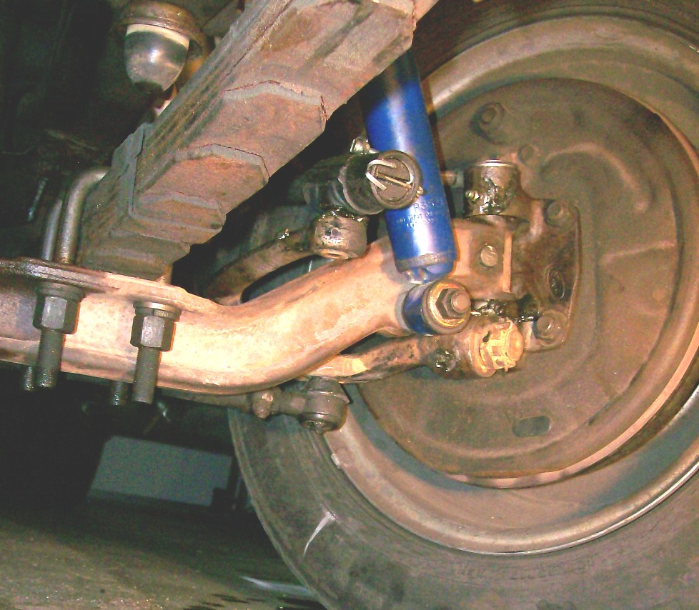
Here is what is on my truck:

Here is the steering upright shown in the No-Limit instructions. Note the difference, notably that the plane on which the new steering arm mounts is "inside" the axis of rotation of the upright. Whereas on my truck that mounting plane is "outside" the axis of rotation.

Perhaps I need to get new uprights.
Any help is appreciated. Thanks.
Gustave
I am trying to install a No-Limit Straight Axle rack & pinion sterring kit.
As I examine what is on my 56 F-100, I am starting to wonder if it is the stock axle. The upright (?) looks a lot different than that shown in the instructions from No-Limit.
It looks like the steering arms provided by No-Limit will line up with holes in the upright (or is it a knuckle?). But it appears they will be spaced farther outwards than shown in the NL instructions (farther towards the wheels). The new steering arms also contact the grease zerk fittings on the front of the uprights.
So, are the steering uprights on my 56 truck even original or stock? Or are they from some other type of year or make?
Does anyone on this list recognize the parts from these photos?
Here is what is on my truck:
Here is the steering upright shown in the No-Limit instructions. Note the difference, notably that the plane on which the new steering arm mounts is "inside" the axis of rotation of the upright. Whereas on my truck that mounting plane is "outside" the axis of rotation.
Perhaps I need to get new uprights.
Any help is appreciated. Thanks.
Gustave
#2
10-22-2009, 09:29 PM

Post Fiend
The pictures you posted are of two different axels and spindles as you mentioned. The upper one looks tremendously familiar. I just pit Kingpins in my 51 and it looks exactly the same - except, yours has been modified with Disc Brakes.
The lower one I don't know.
Here is a picture of my 51 axel and spindles. Edit note:
I'll go shoot a better pic of the drivers side and be right back!
OK here's the pics...these are off my 51. I believe that the 48-52 axels and spindles were the same. But I don't think (and I could be wrong) that the same axels and spindles were used on the Effies.
Here ya go - 1951:
Hope that helps.
Post post edit note. I just looked at the drawings of the two axels in the Illistrated Parts Manual. The axels are very much the same except for the position of the shock absorber stud. You can see on mine that it is clearly on the bottom edge of the axel in a flange. On the 56 it is supposedly in the center of the axel about 1 inch inside the kingpin retainer bolt hole. I can't see yours. But I don't see a hole there or the flange - neither. So, not sure. Can youpost another picture of youaxel where the shock absorber mounts
#3
10-23-2009, 03:18 PM
Update
Julie - thanks for your help. I finally got a hold of Rob at No-Limit. The instructions do not show a 1956 Ford truck specifically. I described my setup and he said that sounded just like the correct 56 parts. He said that the grease fitting should work if it is the 90 degree type (mine is not) and that it is perfectly fine to clearance the new steering arm for the grease nipple. I will swap it to a 90 deg type.
Rob also said on a 56 truck that you remove the steering arms. I am trying to do that now.
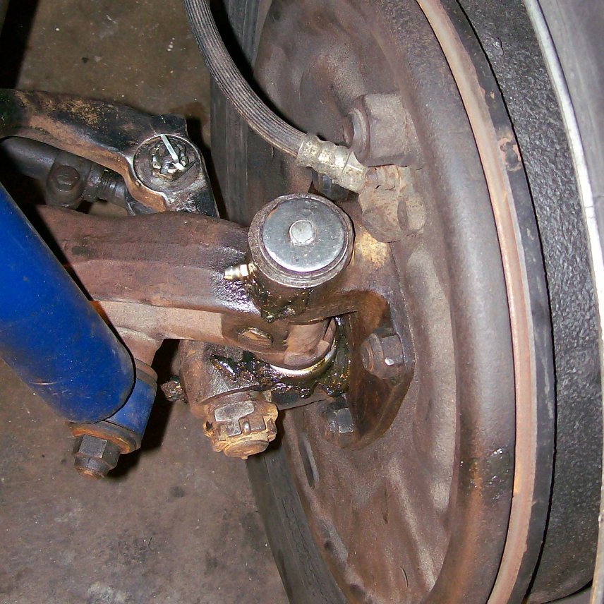
Just for completeness, here is a pic showing how my shock mounts to the axle. It mounts to the bracket that attaches the axle to the leaf spring.

Regards,
Gustave
Rob also said on a 56 truck that you remove the steering arms. I am trying to do that now.
Just for completeness, here is a pic showing how my shock mounts to the axle. It mounts to the bracket that attaches the axle to the leaf spring.
Regards,
Gustave
#4
10-23-2009, 09:08 PM
#5
10-23-2009, 09:37 PM
Dr G
I'm interested in the "rack and pinion" kit for a straight axle. I just recently heard about this option in a mag somewhere. Please give us a review and post photos as you go along. I might want to go this route myself someday, and I'd appreciate your insight.
Thanks Tom
I'm interested in the "rack and pinion" kit for a straight axle. I just recently heard about this option in a mag somewhere. Please give us a review and post photos as you go along. I might want to go this route myself someday, and I'd appreciate your insight.
Thanks Tom
Gustave
#6
10-24-2009, 01:17 AM
Post Fiend
Ok Well that second picture tells a whole new story. Here's a couple of drawings from the "1948-1956 Ford Truck Parts and Accessories Illustrations Catalogue:"
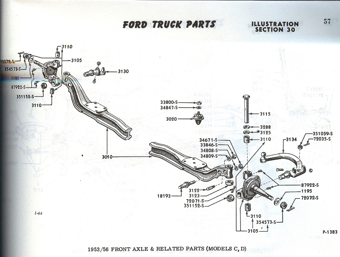
As indicated, this is the stock axel for the 53-56 F-100 Conventional Pick-up (Model C) and F-250 Conventional Pick-up (Model D). Note the position of the second stud (#18193) I was talking about earlier for the shock absorber mount and it's installation position - you no gots. Also not the difference in the steering arm on the passenger side.
Now look at this one - looks more like yours:
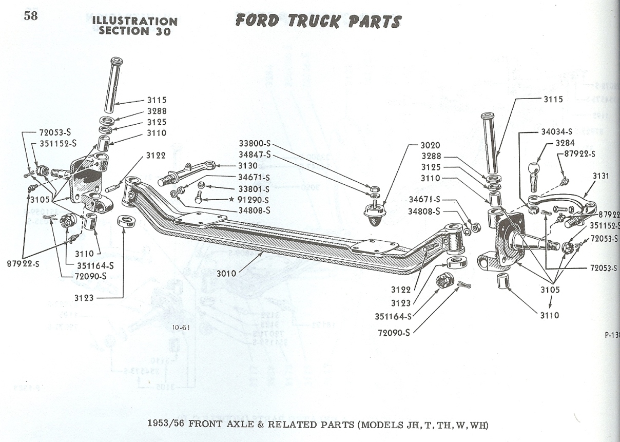
There is no second hole in the axel for the shock mount stud. As a matter of fact there is no shock mount stud at all (probably because of the plate you have bolted to the u-bolts). Also note the shape of the passsenger side steering arm (#3130) and the diagonal flair on the top of it. In your picture, you have this with a square head bolt in it.
This axel (and it seems yours is off) is a 1953-1956 P-500 Parcel Delivery (Model JH); an F-500 Conventional Cab (Model T); and F-600 Conventional Cab (Model TH); a C-500 Cab Forward (Model W); or, a C-600 Cab Forward (Model WH)
Interesting. The P and F Models (P-350 Parcel and F-350 Conventional Cab, resp) have the axel with the shock mount stud in the same place as the F-100 axel drawing - as a matter of fact it looks exactly the same. All the other models have round brake backing plate mounting surfaces as opposed to the "square" ones on yours and the F100 - F-350s.
My corrected guess is a 1953-1956 P/F-500 or P/F-600 Front Axel.
PS. Is your front spring always that flat? If so it's time to respring - it's shot.
As indicated, this is the stock axel for the 53-56 F-100 Conventional Pick-up (Model C) and F-250 Conventional Pick-up (Model D). Note the position of the second stud (#18193) I was talking about earlier for the shock absorber mount and it's installation position - you no gots. Also not the difference in the steering arm on the passenger side.
Now look at this one - looks more like yours:
There is no second hole in the axel for the shock mount stud. As a matter of fact there is no shock mount stud at all (probably because of the plate you have bolted to the u-bolts). Also note the shape of the passsenger side steering arm (#3130) and the diagonal flair on the top of it. In your picture, you have this with a square head bolt in it.
This axel (and it seems yours is off) is a 1953-1956 P-500 Parcel Delivery (Model JH); an F-500 Conventional Cab (Model T); and F-600 Conventional Cab (Model TH); a C-500 Cab Forward (Model W); or, a C-600 Cab Forward (Model WH)
Interesting. The P and F Models (P-350 Parcel and F-350 Conventional Cab, resp) have the axel with the shock mount stud in the same place as the F-100 axel drawing - as a matter of fact it looks exactly the same. All the other models have round brake backing plate mounting surfaces as opposed to the "square" ones on yours and the F100 - F-350s.
My corrected guess is a 1953-1956 P/F-500 or P/F-600 Front Axel.
PS. Is your front spring always that flat? If so it's time to respring - it's shot.
#7
10-24-2009, 01:53 AM
I noted the flat leaf springs myself but had no idea if it was normal or not (I'm used to racecar coil-overs). I did note that there is not a heck of a lot of travel before the axle hits the frame, but it seemed to ride just fine for the short amount of time I drove it. I do like the rake of the truck and the ride height. Re-springing would raise the front so would have to be accompanied by some type of drop axle or something I suppose.
Thanks very much for researching this.
Gustave
Trending Topics
#8
10-24-2009, 03:01 PM
Post Fiend
Wow. That is some usefull information Julie. I've got a lot to learn here obviously. As to the history of my truck, I would not rule anything out. I do know that the PO had a real dislike for anti-seize though! Everything that can be rusted solid, is rusted solid.
I noted the flat leaf springs myself but had no idea if it was normal or not (I'm used to racecar coil-overs). I did note that there is not a heck of a lot of travel before the axle hits the frame, but it seemed to ride just fine for the short amount of time I drove it. I do like the rake of the truck and the ride height. Re-springing would raise the front so would have to be accompanied by some type of drop axle or something I suppose.
Thanks very much for researching this.
Gustave
Tee hee the rake won't be a problem if the back ones are just as bad as the fronts. Sorry to be the bearer of the bad news.
The springs should have a pronounced bow, and the frame at the center above the axel should probably sit 8 to 10 up off the axel. (you look like you have about 2")
PS, When I started my truck, I spent about $300 on manuals and catalogues. Pictures like the ones I posted are invaluable. Especially in light of the fact that the POs may have thrown all different stuff together.
You can get them on CD on E-bay much cheaper. The manual I got this picture out of is $29 for a CD.
Here is a link to a thread we had on Manuals some time ago:
https://www.ford-trucks.com/forums/8...-everyone.html
#9
10-24-2009, 04:14 PM
PS, When I started my truck, I spent about $300 on manuals and catalogues. Pictures like the ones I posted are invaluable. Especially in light of the fact that the POs may have thrown all different stuff together.
You can get them on CD on E-bay much cheaper. The manual I got this picture out of is $29 for a CD.
Here is a link to a thread we had on Manuals some time ago:
https://www.ford-trucks.com/forums/8...-everyone.html
You can get them on CD on E-bay much cheaper. The manual I got this picture out of is $29 for a CD.
Here is a link to a thread we had on Manuals some time ago:
https://www.ford-trucks.com/forums/8...-everyone.html
I just bought a CD copy of "1948-56 Ford Truck Master Parts Catalog". Not sure if that is the same as the "1948-1956 Ford Truck Parts and Accessories Illustrations Catalog" that you refer to in that thread. But it should be better than what I have now. That particular title does not yield anything on Google or eBay right now.
Gustave
<?xml:namespace prefix = o ns = "urn:schemas-microsoft-com
 fficeffice" /><o
 ></o>
></o>
#10
10-24-2009, 04:18 PM
Tee hee the rake won't be a problem if the back ones are just as bad as the fronts. Sorry to be the bearer of the bad news.
The springs should have a pronounced bow, and the frame at the center above the axel should probably sit 8 to 10 up off the axel. (you look like you have about 2")
The springs should have a pronounced bow, and the frame at the center above the axel should probably sit 8 to 10 up off the axel. (you look like you have about 2")
Gustave
#11
10-24-2009, 08:57 PM
Post Fiend
Yep I noticed that. So basically you have no spring travel at all. Is there a rubber bumper bolted to the bottom of the frame to stop the axel? It's P/N 3020 in the drawings above. If you do, it looks like your spring is sitting on that bumper. Ride a little hard? Shoot your springs are worse than mine! (Actually mine aren't too bad but the bushings and frame bolts are as loose as a goose).
The manual I took those from is actually a series of two books - one has all the part numbers and verbal descriptions and is called the "Text" catalogue and the mate is the "Illustrations" Catalogue it has all the exploded drawings like the ones I posted. In the link I attached, it is the Red manual that is pictured.
Everything helps. Your comment about the shop manual is well noted and agreed to. It seems like you need about 3 or 4 manuals to get all the data and pictures you need. Another one is the Owners Manual.
#12
10-25-2009, 07:41 PM
Yep I noticed that. So basically you have no spring travel at all. Is there a rubber bumper bolted to the bottom of the frame to stop the axel? It's P/N 3020 in the drawings above. If you do, it looks like your spring is sitting on that bumper. Ride a little hard?
I have about 2-3 inches of travel before the axle bottoms. Not much I agree. But I do wonder, as the Mid-50's catalog shows a few different "lowering" springs. I can't see how they would lower the truck without also reducing available travel. Maybe not as much. Otherwise you'd have to use a drop-axle or drop spindles (I've not yet seen these for a 56). Or IFS of course, which is probably what most folks do.
Heck, I just want to get back to the point where I can drive the thing. Before I go and start changing springs and such I want to make sure that leaf springs are what I want to stick with for the long haul.
I'll keep looking into the manuals. Thanks for all the help Julie.
Gustave
#13
10-26-2009, 12:37 AM
Dr G
Someone changed your steering over to cross linkage sometime in the past that's why yours looks so different. I bet the pitman shaft (output shaft) on your steering box points at the ground and the pitman arm swings horizontally. If it is power steering it is likely a GM box conversion or a homebrewed adaptation. See pg 136 of the Mid Fifty catalog (download here: http://www.midfifty.com/09cat.pdf ) for a drawing of the gm setup.
Aside: I suggest downloading and printing out the entire catalog or request a copy be mailed to you. Mid Fifty's catalog has a wealth of information and illustrations as well as exploded views and in many ways is much more valuable than the owner's or dealer shop manual since it covers updates and modification parts as well as stock.
Back to the topic at hand. The OEM steering box was manual steer only, the pitman shaft was horizontal and stuck thru a hole in the frame to the outside of the frame. The pitman arm pointed straight down and swung front to back. The pitman arm was connected to the steering arm with a drag link, a bar about 2' long with a "swollen" end at each end that fit over a ball on the pitman arm and the steering arm. The drag link ran parallel to the frame and moved forwards and back when the steering wheel was turned. There was only one simple tie rod that ran from steering arm to steering arm across the truck. Your steering arm has a portion of another arm grafted onto it, I can see the weld in your picture.
I would also hazard a guess that you have lowering springs and possibly a dropped axle on your truck. The instructions for the springs have you use a flat rubber bumper between the frame and the rear center of the spring instead of the OEM above the axle, they are also flat at rest.
Dropped axles often have the shock stud hole filled. Your springs may also have reversed eyes and and a moved forward centerbolt. Check the spring section of the MF catalog for illustrations and explanation of the various modified spring options. You can tell if you have the forward centerbolts by looking at your truck from the side while sitting on it's wheels. For some unknown reason the stock centerbolt position places the axle (and therefore the wheels) about 1 1/4" rearward of being centered in the fender arches on all 53-56 F100s. This gives an awkward unbalanced look to the front of the truck. The forwards centerbolt springs moves the axle forwards to center the wheels in the fender arches. If your wheels sit off center to the rear, you have OEM centerbolt placement. If the wheels are centered you have centerbolt forward springs.
Too bad you hadn't asked here or checked the articles archive before buying that R&P steering kit. The jury is still out on that kit. Many here have found the Toyota 4x4 power steering box swap a much less expensive bolt in swap that works so well it's almost like it was made for the Effie.
#14
10-26-2009, 11:12 AM
Dr G
Someone changed your steering over to cross linkage sometime in the past that's why yours looks so different. I bet the pitman shaft (output shaft) on your steering box points at the ground and the pitman arm swings horizontally. If it is power steering it is likely a GM box conversion or a homebrewed adaptation. See pg 136 of the Mid Fifty catalog (download here: http://www.midfifty.com/09cat.pdf ) for a drawing of the gm setup.
Aside: I suggest downloading and printing out the entire catalog or request a copy be mailed to you. Mid Fifty's catalog has a wealth of information and illustrations as well as exploded views and in many ways is much more valuable than the owner's or dealer shop manual since it covers updates and modification parts as well as stock.
Yes, my 56 has the GM box conversion. The old box leaked like a sieve when I got the truck, so I bought a new (rebuilt) one (for a 72 Nova in this case). I installed it and bled the system with a friend. That is when we noticed the severe deficiency of that conversion system. By rotating the pitman arm 90 deg, it now puts a large twisting moment on the frame. I had read in the MF catalog that the frame should be re-enforced for this kit, now I understood why. My frame has not been reinforced.
We first noticed the frame flex when bleeding the system. My buddy noticed the flex standing out in front of the truck to top off the PS fluid. He said it only did it at full lock. But during a test drive, with the tires provided resistive torque to steering inputs, we realized that the steering column was moving left and right (through the oversized hole in the floor board) as the pitman arm twisted the frame. I was shocked, and being an ME was not willing to live with this type of system.
So it was either go to the popular (more stock-like) Toyota box, where the pitman arm loads the frame along its axis, or try this R&P system.
I did a lot of reading here on the forum, using search, though I did not ask any questions specifically. Though even if the jury had been mixed, I�d still have opted to give this R&P system a try. The problems I am having are nothing to do with that R&P system, just problems with an old rusty truck, lack of familiarity, and bad maintenance by the PO. I am not crazy about the added un-sprung mass, but on a truck like this it might not matter that much. The telescopic steering column will be constantly changing length as the suspension moves, but then that is no different than a driveshaft so should not be an issue. We�ll see how it goes once I can get to the point of actually installing it.
I would also hazard a guess that you have lowering springs and possibly a dropped axle on your truck. The instructions for the springs have you use a flat rubber bumper between the frame and the rear center of the spring instead of the OEM above the axle, they are also flat at rest.
Dropped axles often have the shock stud hole filled. Your springs may also have reversed eyes and and a moved forward centerbolt. Check the spring section of the MF catalog for illustrations and explanation of the various modified spring options. You can tell if you have the forward centerbolts by looking at your truck from the side while sitting on it's wheels. For some unknown reason the stock centerbolt position places the axle (and therefore the wheels) about 1 1/4" rearward of being centered in the fender arches on all 53-56 F100s. This gives an awkward unbalanced look to the front of the truck. The forwards centerbolt springs moves the axle forwards to center the wheels in the fender arches. If your wheels sit off center to the rear, you have OEM centerbolt placement. If the wheels are centered you have centerbolt forward springs.
Dropped axles often have the shock stud hole filled. Your springs may also have reversed eyes and and a moved forward centerbolt. Check the spring section of the MF catalog for illustrations and explanation of the various modified spring options. You can tell if you have the forward centerbolts by looking at your truck from the side while sitting on it's wheels. For some unknown reason the stock centerbolt position places the axle (and therefore the wheels) about 1 1/4" rearward of being centered in the fender arches on all 53-56 F100s. This gives an awkward unbalanced look to the front of the truck. The forwards centerbolt springs moves the axle forwards to center the wheels in the fender arches. If your wheels sit off center to the rear, you have OEM centerbolt placement. If the wheels are centered you have centerbolt forward springs.

It could be a dropped axle (the PO stated it was stock though), it is not tubular, but looks to be a factory-like cast piece. All of dropped axles I�ve seen list in vendor catalogs and websites are fabricated tubular items. Maybe someone made stock-looking ones in the past?
Thanks for taking the time to explain all of this.
Gustave
#15
10-26-2009, 12:51 PM
Yes, and some still do. The tubular assembled dropped axles are a fairly new product. Previously all dropped axles were remanufactured from stock axles by reforming the portion between the spring mount and the kingpin boss. Most were done in small garage operations with varied quality. Some droppers filled the recess in the axle ends to mask the quality of the stretching or to clean up the appearance. Here's a pretty good comparison of dropped stock axle quality: Dropped front axles
Since good core axles are over 50 years old and in demand by restorers plus the legal issues of product liability, plus the time to search out, clean up and check core axles, the new assembled axle came about.
No OEM springs were reverse eye, and with the flat posture and relocated bumper it is likely that you have dropped springs. You can tell if you have the forward centerbolt by measuring the wheel base. Stock is 110", CB forward would measure 111 + ".
As far as the rusted fastener issue, get a large can of Liquid Wrench and liberally spray every fastener you can find once or twice a day for 3-4 days prior to working with them. If you have a suitable compressor get yourself a GOOD air ratchet gun (I really like the compact size Air Cat brand for quality and power in an easy to use sized package at a fair price. It is also conservative in air use so can be used with a small portable contractor's compressor such as used with nail guns) If you do not have air available I'd suggest investing in an 18V lithium battery Millwaukee cordless ratchet gun.
Complement the gun with a set of Craftsman or Kobalt 6 point sockets (not impact sockets, but standard wall. Impact sockets often don't fit where you need them to and the forementioned brands have a lifetime guarantee, should one fail in use return it for a no questions replacement.) Hold the other end of the bolt or nut with a 6 point box wrench.
Either of the guns recommended will remove the fastener or snap it off (sometimes faster if it is just a standard nut and bolt you plan to replace anyhow.) Between the penetrating oil and the power ratchet you'll have fasteners flying all around you as you power thru dissassembly.

