Bronco SAS with 1 ton gear
#121
 12-14-2009, 02:28 AM

Just bumping this one back up, curious what your front driveshaft and transmission crossmember ended up looking like.
I've got basically the same setup in the front of my F250 now(ended up doing the shackle reversal) and I have serious driveshaft issues. It was hitting the crossmember with the 60 and the TTB springs, now with it laying on the crossmember it is 2" above the pinion at ride height and I am pretty certain a long travel CV shaft is in order.
I've got basically the same setup in the front of my F250 now(ended up doing the shackle reversal) and I have serious driveshaft issues. It was hitting the crossmember with the 60 and the TTB springs, now with it laying on the crossmember it is 2" above the pinion at ride height and I am pretty certain a long travel CV shaft is in order.
All three Broncos have bone stock x-members, and almost stock driveshafts. No modifications to anything other than the 1350 yoke for the rear of the black Bronco. Even that was a simple fix.
IN the case of the F250, the x-member either has to be replaced or modified.
I dont believe this is a huge issue, and I remember seeing many options on this site.
As far as my builds go, these Broncos required minimal effort to complete.
#122
12-14-2009, 10:27 AM
I'm going to try and dig up a later model crossmember to put in there, the 90's stuff does have alot more drop in it if memory serves. I may end up building something new, as it won't be notching the crossmember so much as cutting it in two and tying it back together.
It really looks like I'm going to need a dual cardan joint at the case though, the yokes at that end were almost touching sitting at ride height.
This is what I'm dealing with crossmember wise, as you can see it barely cleared bone stock with the TTB still in it:
http://www.bigblocksix.com/f100swb/f...7/exhaust1.jpg
I was going to take some pictures of what I have going on under there now but my stupid camera died on me... LOL
#123
12-14-2009, 10:42 AM
I see how that coule be a problem, however, I dont see that as anything that a custom x-member cant fix.
I have seen several solutions for this problem. Anything from a complete custom unit, to a simple piece of tube cut in half and placed where a section of the corssmember has been removed where the driveshaft would hit.
I have seen several solutions for this problem. Anything from a complete custom unit, to a simple piece of tube cut in half and placed where a section of the corssmember has been removed where the driveshaft would hit.
#125
12-14-2009, 04:04 PM
I'm going to see what I can scrounge up for stock stuff here this week. I'll probably end up fabbing something up, but, the less fabwork the better, using a buddys shop and materials, and only have weekends to work on it, plus it's -30... LOL
If you're getting away without a CV on the front shaft, I guess I'm going to have to flex the thing out and see just what happens. I also need to check my caster angle, pinion angle looks ok, but I haven't checked the caster yet, so, things could get better, or worse.
If you're getting away without a CV on the front shaft, I guess I'm going to have to flex the thing out and see just what happens. I also need to check my caster angle, pinion angle looks ok, but I haven't checked the caster yet, so, things could get better, or worse.
#128
12-14-2009, 06:38 PM
#129
12-14-2009, 06:41 PM
Lead Driver
#130
12-17-2009, 07:15 PM
Hey Ed, I got a spring shackle ?
Looks like you are keeping busy with your new toy, love looking at your work.
I was wondering what would happen if the spring shackle mount was made to fit through the frame instead of below it, as yours is? Seems like some of the older trucks were like that from the factory. My reason for asking is, if this was done, it would put the axle closer to the stock height while doing the shackle reversal. The front mount could then be shortened also. The body mount may need to be modified some. Any thoughts?
I was wondering what would happen if the spring shackle mount was made to fit through the frame instead of below it, as yours is? Seems like some of the older trucks were like that from the factory. My reason for asking is, if this was done, it would put the axle closer to the stock height while doing the shackle reversal. The front mount could then be shortened also. The body mount may need to be modified some. Any thoughts?
#131
12-17-2009, 07:40 PM
Lead Driver
I'm not Ed - but maybe I can help.
The shackles going through the frame like on the 70's (60's as well?) trucks are 2 piece shackles.
Like this.
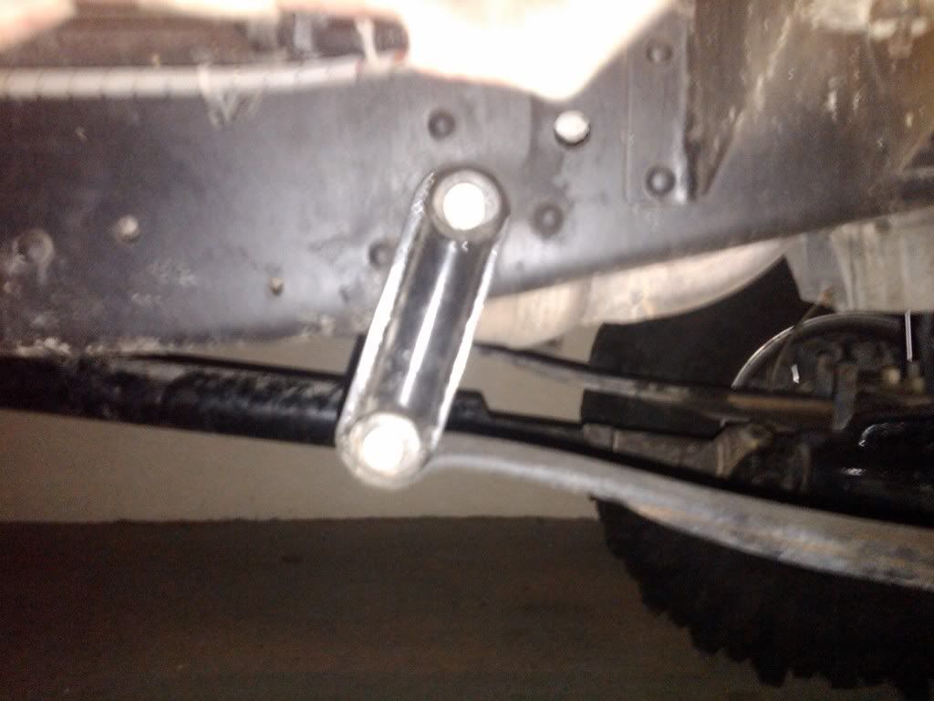
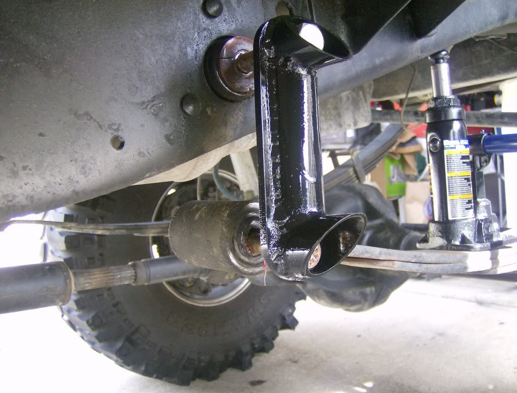
This is what the "hanger" looks like that is rivited to the stock frame and serves as the shackle pivot

Based on this picture of where the rear shackle mounts on Ed's black bronco - I think it could be hard to work.
As for your theory - yes, these type of shackles could work to keep the ride height lower. You'd just have to mess with a different setup for the front hangers as well seeing as it looks like they would head up into the frame.
The shackles going through the frame like on the 70's (60's as well?) trucks are 2 piece shackles.
Like this.
This is what the "hanger" looks like that is rivited to the stock frame and serves as the shackle pivot
Based on this picture of where the rear shackle mounts on Ed's black bronco - I think it could be hard to work.
As for your theory - yes, these type of shackles could work to keep the ride height lower. You'd just have to mess with a different setup for the front hangers as well seeing as it looks like they would head up into the frame.
#133
12-18-2009, 12:44 PM
Elder User
Join Date: Feb 2006
Location: Cascade, ID
Posts: 788
Likes: 0
Received 0 Likes
on
0 Posts
#135
12-24-2009, 04:12 PM
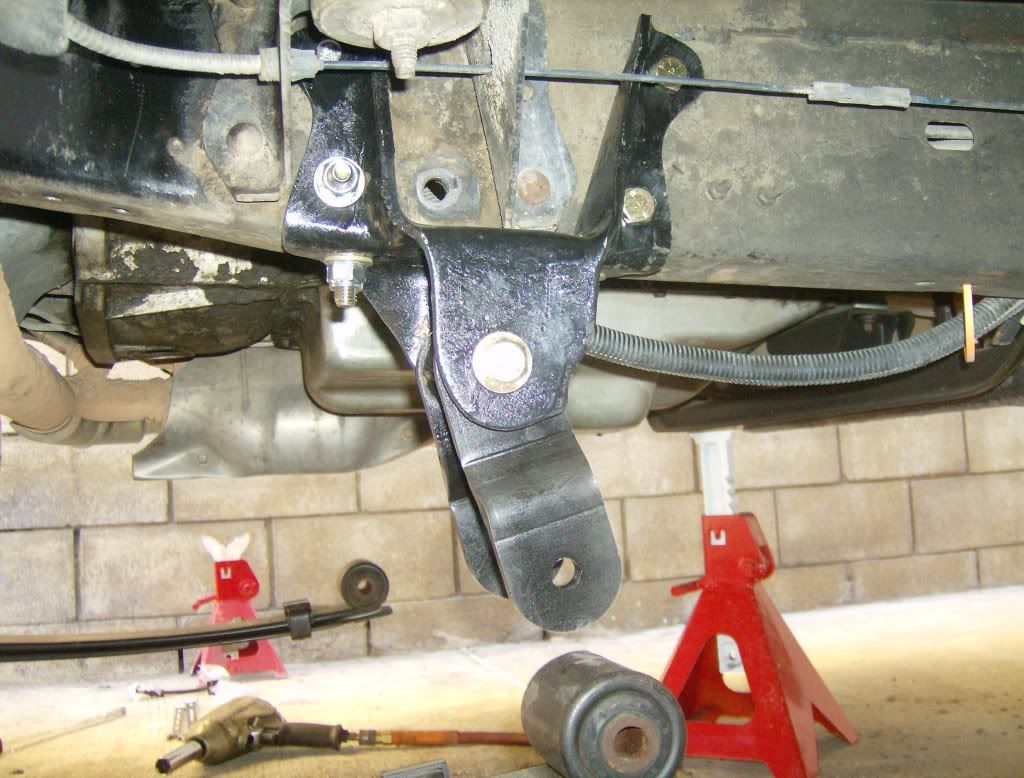
Interesting question, as this plaqued me for quite a few days prior to tearing into these things.
From a mechanical aspect the crumple zone is designed to crumple or fold when a direct force is placed upon the area in a straigh line. Meaning a direct impact to the frontal area, and not the sides. I understand that this design maintians structural integrity with regards to side loads, and is only affected by frontal impacts.
That being said, I feel comfortable with the placement of the hanger in this area.
I have re-enforced one, and left another alone. Both have had recovery equipment attached to these areas with no damage or any sign of bending.
Notice that the two sides are tied togther, and the idea is to again place a 2" reciever between the two side, to further aid in strength.
I do not believe that these areas are of a terrible concern as far as strength goes, but the crumple zone design no longer works.
This is now a rigid design, and will never work as the original engineers designed it.