Night vision in an X - anyone with some good advice?
#1
 08-18-2009, 05:43 PM

Join Date: Jan 2009
Location: Lake Orion, MI.
Posts: 84
Likes: 0
Received 0 Likes
on
0 Posts
Night vision in an X - anyone with some good advice?
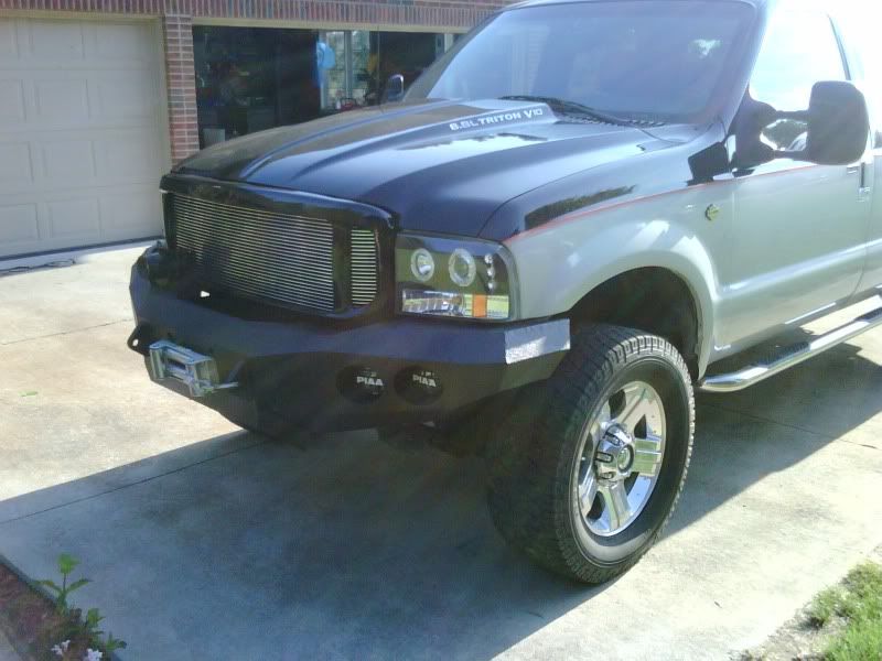
I just picked up a new Cadillac NightVision Camera, and will use it in my Excursion. Anyone done this? I am contemplating removing one of the four PIAA foglights or leaving it behind the bumper where the winch currently sits. (It is going anyway...).
Anyone with some good advice here?
Anyone with some good advice here?
#2
08-18-2009, 07:27 PM
Join Date: Jan 2009
Location: Lake Orion, MI.
Posts: 84
Likes: 0
Received 0 Likes
on
0 Posts
...and some wiring ideas. I don't want to trial and error since the cameras are so expensive.
Here is where I am:
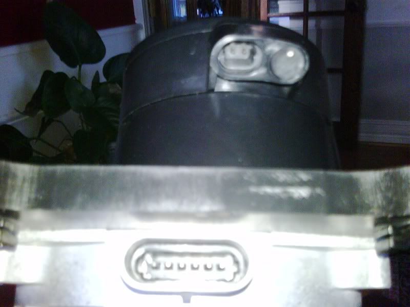
Camera with two connectors, one two pin and one six pin connector:
Here is the wiring diagram for the camera:

and

so I am missing where I feed power, and where I pick up my video. Anyone with a good idea?
Thanks in advance,
Anders
Here is where I am:
Camera with two connectors, one two pin and one six pin connector:
Here is the wiring diagram for the camera:
and
so I am missing where I feed power, and where I pick up my video. Anyone with a good idea?
Thanks in advance,
Anders
#3
08-18-2009, 07:42 PM
Post Fiend
Join Date: May 2006
Location: Central Florida
Posts: 10,007
Likes: 0
Received 0 Likes
on
0 Posts
The first diagram has the video source, it's the high and low video reference lines. I suspect that is the signal and return, being two wire I don't think you have to use coax, just shield your reference wires.
Power comes from the fuse distribution, it looks like it goes into C2 of the camera. Another wire in the C2 plug handles ground. It also appears that one of the terminals in C1 plug has a ground.
What are you going to use to view the system?
Power comes from the fuse distribution, it looks like it goes into C2 of the camera. Another wire in the C2 plug handles ground. It also appears that one of the terminals in C1 plug has a ground.
What are you going to use to view the system?
#4
08-18-2009, 07:52 PM
Join Date: Jan 2009
Location: Lake Orion, MI.
Posts: 84
Likes: 0
Received 0 Likes
on
0 Posts
The first diagram has the video source, it's the high and low video reference lines. I suspect that is the signal and return, being two wire I don't think you have to use coax, just shield your reference wires.
Power comes from the fuse distribution, it looks like it goes into C2 of the camera. Another wire in the C2 plug handles ground. It also appears that one of the terminals in C1 plug has a ground.
What are you going to use to view the system?
Power comes from the fuse distribution, it looks like it goes into C2 of the camera. Another wire in the C2 plug handles ground. It also appears that one of the terminals in C1 plug has a ground.
What are you going to use to view the system?
OK so is it safe to assume power feed on the top connector and signal on the bottom? Does it start A-B-C-D-E-F or how will I know which pin is which?
I have a Cadillac HUD on the way, might just carve a hole in the top dashboard and drop it down. Otherwise separate display somewhere in front of me....
#5
08-18-2009, 08:04 PM
Post Fiend
Join Date: May 2006
Location: Central Florida
Posts: 10,007
Likes: 0
Received 0 Likes
on
0 Posts
C1 is the 6 pin connector. C & D pins in C1 is the signal, but the shielding is connected to Pin J of the HUD. Pin A on C1 is a 14 volt reference voltage. So that leaves b, e, f, it looks like C1 pin E is ground on design 1 and pin B is ground on design 2. If I am reading it correctly, on design 1 you supply power to pin F, which would use all of the pins. On design 2, C2 pin A is power and C2 pin B is ground.
#6
08-18-2009, 08:54 PM
Join Date: Jan 2009
Location: Lake Orion, MI.
Posts: 84
Likes: 0
Received 0 Likes
on
0 Posts
C1 is the 6 pin connector. C & D pins in C1 is the signal, but the shielding is connected to Pin J of the HUD. Pin A on C1 is a 14 volt reference voltage. So that leaves b, e, f, it looks like C1 pin E is ground on design 1 and pin B is ground on design 2. If I am reading it correctly, on design 1 you supply power to pin F, which would use all of the pins. On design 2, C2 pin A is power and C2 pin B is ground.
</TH></TR><TR><TH vAlign=center align=middle colSpan=2>Connector Part Information
</TH><TH vAlign=center align=left colSpan=2><TABLE border=0><TBODY><TR><TD vAlign=top>• </TD><TD vAlign=top>12162209</TD></TR></TBODY></TABLE><TABLE border=0><TBODY><TR><TD vAlign=top>• </TD><TD vAlign=top>6-Way F Metri-Pack 150.2 Series, Pull-to-Seat, Sealed (BLK)</TD></TR></TBODY></TABLE></TH></TR><TR><TH vAlign=bottom align=middle>Pin
</TH><TH vAlign=bottom align=middle>Wire Color
</TH><TH vAlign=bottom align=middle>Circuit No.
</TH><TH vAlign=bottom align=middle>Function
</TH></TR><TR><TD vAlign=center align=middle>A
</TD><TD vAlign=center align=middle>PNK
</TD><TD vAlign=center align=middle>608
</TD><TD vAlign=center align=left>14 Volt Reference
</TD></TR><TR><TD vAlign=center align=middle>B
</TD><TD vAlign=center align=middle>BLK/WHT
</TD><TD vAlign=center align=middle>351
</TD><TD vAlign=center align=left>Ground
</TD></TR><TR><TD vAlign=center align=middle>C
</TD><TD vAlign=center align=middle>YEL
</TD><TD vAlign=center align=middle>2385
</TD><TD vAlign=center align=left>Night Vision Video Low Signal
</TD></TR><TR><TD vAlign=center align=middle>D
</TD><TD vAlign=center align=middle>DK GRN
</TD><TD vAlign=center align=middle>2386
</TD><TD vAlign=center align=left>Night Vision Video High Signal
</TD></TR><TR><TD vAlign=center align=middle>E
</TD><TD vAlign=center align=middle>BLK/WHT
</TD><TD vAlign=center align=middle>151
</TD><TD vAlign=center align=left>Ground
</TD></TR><TR><TD vAlign=center align=middle>F
</TD><TD vAlign=center align=middle>BRN
</TD><TD vAlign=center align=middle>741
</TD><TD vAlign=center align=left>Ignition 3 Voltage
</TD></TR></TBODY></TABLE>
<TABLE width="95%" border=1><TBODY><TR><TH vAlign=center align=middle colSpan=4>
</TH></TR><TR><TH vAlign=center align=middle colSpan=2>Connector Part Information
</TH><TH vAlign=center align=left colSpan=2><TABLE border=0><TBODY><TR><TD vAlign=top>• </TD><TD vAlign=top>15324922</TD></TR></TBODY></TABLE><TABLE border=0><TBODY><TR><TD vAlign=top>• </TD><TD vAlign=top>6-Way F Metri-Pack 150.2 Series, Pull-to-Seat, Sealed (BLK)</TD></TR></TBODY></TABLE></TH></TR><TR><TH vAlign=bottom align=middle>Pin
</TH><TH vAlign=bottom align=middle>Wire Color
</TH><TH vAlign=bottom align=middle>Circuit No.
</TH><TH vAlign=bottom align=middle>Function
</TH></TR><TR><TD vAlign=center align=middle>A
</TD><TD vAlign=center align=middle>PNK
</TD><TD vAlign=center align=middle>608
</TD><TD vAlign=center align=left>14 Volt Reference
</TD></TR><TR><TD vAlign=center align=middle>B
</TD><TD vAlign=center align=middle>BLK/WHT
</TD><TD vAlign=center align=middle>351
</TD><TD vAlign=center align=left>Ground
</TD></TR><TR><TD vAlign=center align=middle>C
</TD><TD vAlign=center align=middle>YEL
</TD><TD vAlign=center align=middle>2385
</TD><TD vAlign=center align=left>Night Vision Video Low Signal
</TD></TR><TR><TD vAlign=center align=middle>D
</TD><TD vAlign=center align=middle>DK GRN
</TD><TD vAlign=center align=middle>2386
</TD><TD vAlign=center align=left>Night Vision Video High Signal
</TD></TR><TR><TD vAlign=center align=middle>E
</TD><TD vAlign=center align=middle>--
</TD><TD vAlign=center align=middle>--
</TD><TD vAlign=center align=middle>Not Used
</TD></TR><TR><TD vAlign=center align=middle>F
</TD><TD vAlign=center align=middle>--
</TD><TD vAlign=center align=middle>--
</TD><TD vAlign=center align=middle>Not Used
</TD></TR></TBODY></TABLE>
Thank you very much ReAX!!!
#7
08-18-2009, 09:41 PM
Post Fiend
Join Date: May 2006
Location: Central Florida
Posts: 10,007
Likes: 0
Received 0 Likes
on
0 Posts
Trending Topics
#8
08-18-2009, 11:30 PM

let us know what the wiring coming off the vision display looks like.
you are going to want shielded wire (referenced to the drain wire) for the high and low video signals. This shields the signals from each other, and from any high frequency audio that might get picked up. The tricky part, if it isn't in the display, is that you gotta figure out a regulated buck/boost 14V supply. Video doesn't like it's reference signal moving around.
If I can catch my apps engineer this week, I'll show him the schematic and see what he thinks. Like I said though, it might be easier to figure it out once you have the other half.
That's friggin' sweet by the way.
#9
08-19-2009, 09:58 PM
Join Date: Jan 2009
Location: Lake Orion, MI.
Posts: 84
Likes: 0
Received 0 Likes
on
0 Posts
C1 is the 6 pin connector. C & D pins in C1 is the signal, but the shielding is connected to Pin J of the HUD. Pin A on C1 is a 14 volt reference voltage. So that leaves b, e, f, it looks like C1 pin E is ground on design 1 and pin B is ground on design 2. If I am reading it correctly, on design 1 you supply power to pin F, which would use all of the pins. On design 2, C2 pin A is power and C2 pin B is ground.
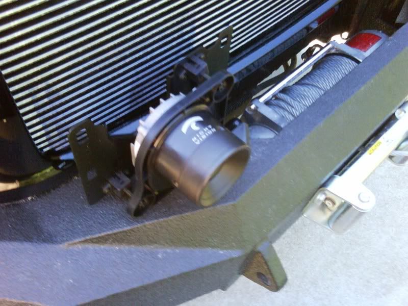
I will mount it behind the square opening in my Iron Bull bumper and use a plexiglass cover for protection of the camera against rocks, etc. Just looked into an AAXA pico P2 projector. That might be more fun as a HUD than the old VFD tubes. They are getting so small and at 60 lumens should be fine for driving at night. Maybe use my inner PIAA lights for illuminators. Depends on how well it does without any support light in the thermal wavelength.
#10
08-20-2009, 10:33 AM
Post Fiend
for the wires why dont you get a pig tail for the camara? the plugs look very particular type and would be hard to get wires onto, and same goes for the HUD that way it just a matter of red to red blue to blue....
where do the cadillacs mount the camara, i would try to put it in the same place they do, there are people that get paid BIG bucks to find the right spot for it trust them.
where do the cadillacs mount the camara, i would try to put it in the same place they do, there are people that get paid BIG bucks to find the right spot for it trust them.
#11
08-20-2009, 11:53 AM
Join Date: Jan 2009
Location: Lake Orion, MI.
Posts: 84
Likes: 0
Received 0 Likes
on
0 Posts
I am mounting it in the middle of my front bumper, which would be elevated compared to a Cadillac grille. That should be OK. The glass would protect the lens from a $2,600 lens damage...
#12
08-20-2009, 12:01 PM
Post Fiend
Join Date: May 2006
Location: Central Florida
Posts: 10,007
Likes: 0
Received 0 Likes
on
0 Posts
#13
08-20-2009, 12:46 PM
Join Date: Jan 2009
Location: Lake Orion, MI.
Posts: 84
Likes: 0
Received 0 Likes
on
0 Posts
Maybe something like this:
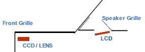
The LCD would be my projector.
What do you think?
#14
08-20-2009, 01:03 PM
Post Fiend
Join Date: May 2006
Location: Central Florida
Posts: 10,007
Likes: 0
Received 0 Likes
on
0 Posts
I honestly don't know enough about the systems, but it was my understanding the early gens of HUDs worked by shining a light through an LCD to project the image on to another surface. Typically I though the display surface was separate from the wind screen as it has to be adjusted to reflect the projection back toward the driver and had a somewhat limited field of view.
If that's the way your mspaint is working, the top will be much wider than the bottom because of the different lengths and might make it a pain to focus. I'd still love to see how it comes out and how you like it, but it seems like a lot of work in just the planning phase.
If that's the way your mspaint is working, the top will be much wider than the bottom because of the different lengths and might make it a pain to focus. I'd still love to see how it comes out and how you like it, but it seems like a lot of work in just the planning phase.
#15
08-26-2009, 01:09 PM
Sorry I haven't been able to check with my apps guy on the wiring yet.
REAx is right - LCD projectors worked by shining a backlight through an LCD module to porject an image. Same way that most of the "projector" type TV systems work as well.
Also, as REAx pointed out, you are going to see some keystoning issues (image will be skewed larger at the top though, since it has a longer focal length) You might be able to get around this issue if the lower LCD mount is adjustable with regards to how it shines against the first mirror. I'd build some flexibility into the mounts to adjust for the focal length top & bottom.
Last - might be something to check out, but I think the caddies have a mirrored finish on the windshield - in the image you put up, you are shining up through the lcd onto the mirror, then onto the windscreen, but.....you gotta reflext the image back rather than sending it out into space through the windshield! The doubled mirror should image will also take care of the image refraction / flipping.