intresting engine stand

 ffice
ffice ></o
></o
#2
 08-18-2009, 05:30 AM
Join Date: Apr 2007
Location: Olympia Wa
Posts: 200
Likes: 0
Received 0 Likes
on
0 Posts
Engine Stand Project
I decided that it would be nice to have an engine run-in stand. A place to bolt a motor, then fire it up and run it for break-in, tuning, and to find and fix any problems, such as leaks, before doing the final motor installation.
You can buy some stands, but they aren’t cheap, and then involve truck shipping since they are so large. Plus, its fun to build things.
Here’s what I built:
I decided to make it out of 2” square tubing. I bought some heavy stuff with 0.12” thick walls. I made the overall size of the base 30” by 60”. A friend donated some extra casters he had. It’s important that the stand be high enough so that the legs of your engine hoist will roll below. In this case, 7 �” was just enough for my hoist.
At one end, I welded on two uprights. This is for mounting the radiator and control panel.
From Pull-A-Part, I got a Camaro radiator along with its cooling fan. A Nissan at the same yard donated a radiator overflow tank. I used the rubber pads from the Camaro top and bottom to mount it. The fan in the car was used in a pulling configuration (mounted behind the radiator). I tried it in both directions by changing wire polarity, and it worked, but was drawing very heavy current. I’m not sure if I caused that by running it backwards, or whether it was just defective, but another trip to Pull-A-Part secured another fan that works fine without drawing too much current. I’ve just let it run its normal direction though, I don’t want to risk making another trip.
Below the radiator, I mounted a battery (with disconnect ****), a fuel tank, an electric fuel pump with regulator and pressure gauge, and a fuel filter. Also mounted on the uprights is a fire extinguisher – I hope it’s never necessary, but nice to have just in case.
For the control panel, I used some �” square tubing and aluminum sheet. I mounted a tachometer (from a boat), a TachMatch so it can be switched to accommodate engines with different number of cylinders, a voltmeter, oil pressure gauge, and a water temperature gauge. I also put in an extra hole for future, which I temporarily filled with another oil pressure gauge.
When I was buying the small gauges at Summit, I also ordered a Moroso switch panel. This has a starter button, and a number of switches with on-indicator lamps, and a fuse per switch. I wired it up so that I have an on/off switch for the ignition which also powers the other gauges, the starter switch, a fuel pump switch, and a fan switch. That leaves a couple switches for future expansion.
I used several relays in the wiring. There’s a horn relay used to switch the fan, and another to switch the ignition current. I also got a starter relay from a Ford at Pull-A-Part so that the cable connecting from the battery to the starter is only active when the starter button is pushed. This is necessary for cars without starter relays (like Fords), but is also compatible with cars that use a solenoid on the starter. I like this approach since there’s less likelihood that you will accidently connect the high-current cable to something bad when it is hot. On the other side of the stand, I installed a ground cable.
I’ve made two motor adaptors so far. One is for a flathead Ford V8, and the other is for a small-block Ford V8 (289, 302, 351). These are simply cradles with rubber mounts. I used common inexpensive transmission mounts that connects the cradle to the motor. The cradle clamps to the main 2x2 frame so that it can easily be adjusted back and forth.
At the transmission end, I made a plate that bolts where the transmission typically would mount. I drilled patterns in the plate for three common Chevy and Ford patterns. The plate connects to the frame via a couple more transmission mounts, same as in the front.
Once I had it all welded up, I took it down to the local powder-coating company and had them powder-coat everything. I figure since it was going to be exposed to gas, oil, hot water and abrasion, it needed to be tough. They charged $100 for the job. Here are all the parts ready to be coated:
The first motor I ran on it was a Ford flathead V8. It was expensive to hook up the radiator since these motors have two water pumps and two hoses per pump. However, 16 connections and hose clamps later it ran without leaking. The radiator cooled it well, and the vibration when running was minimal.
With this motor, the gauges worked a little strange. As I revved the motor, they would start fluctuating wildly at times. I’m not sure why this is. It may be interference from the ignition wiring, in which case I might need to make a grounded shield for the back of the instruments. I bought inexpensive generic Summit electronic gauges, so that may be the problem, I’ll wait until I do the next motor to see if it’s a chronic issue or unique to this motor.
Update:
I've run my second motor on it, a Ford 302 stroker motor. In order to make it work, I had to add an MSD ignition and coil to the stand, which I did below the radiator on the "drivers" side. That was because I was using a magnetically triggered distributor that couldn't directly run a coil.
Here's what it looks like with this motor:
I found that the gauges work fine with this project. I had installed both mechanical and electrical oil pressure gauges on the instrument panel since I had an extra hole for expansion - this motor had an oil pressure "issue" and it was nice to have both gauges to be able to confirm proper operation of the gauge and sender. At the local Pull-A-Part I found a single top hose that worked, and was able to cut up and join four for the bottom hose. Lots of clamps, but inexplicably it doesn't leak.
I had put some extra caster pads in the middle of the stand, just in case I needed them. As it turns out, I didn't need them, and the middle pads are about where the front motor mount wants to be with this motor. I suppose I should have left the pads off. This is a high power motor though, and when you hit it, there is some flex in the stand.
One other minor change I would make. I wired it so that the gauges turned on with the ignition. Next time, I would have a separate switch for the gauges. This would allow you to leave the ignition off, but still turn over the motor and watch the oil pressure gauge as you prime the oil system prior to fire-up.
The stand saved a lot of work on this project. I had made an assembly error on this motor. So in addition to getting the motor tuned up and tested, it allowed me to find the problem and easily fix it prior to installing the motor in the car (and having to pull it again).
PS - this is a LOUD motor with little 12" long straight pipes. What little hearing I used to have must be even less now. Would be nice to have a muffler set-up. Better yet, also a way to run the exhaust outside the shop. Not that the entire stand can't be rolled outside.
LaineFamily home page...
I decided that it would be nice to have an engine run-in stand. A place to bolt a motor, then fire it up and run it for break-in, tuning, and to find and fix any problems, such as leaks, before doing the final motor installation.
You can buy some stands, but they aren’t cheap, and then involve truck shipping since they are so large. Plus, its fun to build things.
Here’s what I built:
I decided to make it out of 2” square tubing. I bought some heavy stuff with 0.12” thick walls. I made the overall size of the base 30” by 60”. A friend donated some extra casters he had. It’s important that the stand be high enough so that the legs of your engine hoist will roll below. In this case, 7 �” was just enough for my hoist.
At one end, I welded on two uprights. This is for mounting the radiator and control panel.
From Pull-A-Part, I got a Camaro radiator along with its cooling fan. A Nissan at the same yard donated a radiator overflow tank. I used the rubber pads from the Camaro top and bottom to mount it. The fan in the car was used in a pulling configuration (mounted behind the radiator). I tried it in both directions by changing wire polarity, and it worked, but was drawing very heavy current. I’m not sure if I caused that by running it backwards, or whether it was just defective, but another trip to Pull-A-Part secured another fan that works fine without drawing too much current. I’ve just let it run its normal direction though, I don’t want to risk making another trip.
Below the radiator, I mounted a battery (with disconnect ****), a fuel tank, an electric fuel pump with regulator and pressure gauge, and a fuel filter. Also mounted on the uprights is a fire extinguisher – I hope it’s never necessary, but nice to have just in case.
For the control panel, I used some �” square tubing and aluminum sheet. I mounted a tachometer (from a boat), a TachMatch so it can be switched to accommodate engines with different number of cylinders, a voltmeter, oil pressure gauge, and a water temperature gauge. I also put in an extra hole for future, which I temporarily filled with another oil pressure gauge.
When I was buying the small gauges at Summit, I also ordered a Moroso switch panel. This has a starter button, and a number of switches with on-indicator lamps, and a fuse per switch. I wired it up so that I have an on/off switch for the ignition which also powers the other gauges, the starter switch, a fuel pump switch, and a fan switch. That leaves a couple switches for future expansion.
I used several relays in the wiring. There’s a horn relay used to switch the fan, and another to switch the ignition current. I also got a starter relay from a Ford at Pull-A-Part so that the cable connecting from the battery to the starter is only active when the starter button is pushed. This is necessary for cars without starter relays (like Fords), but is also compatible with cars that use a solenoid on the starter. I like this approach since there’s less likelihood that you will accidently connect the high-current cable to something bad when it is hot. On the other side of the stand, I installed a ground cable.
I’ve made two motor adaptors so far. One is for a flathead Ford V8, and the other is for a small-block Ford V8 (289, 302, 351). These are simply cradles with rubber mounts. I used common inexpensive transmission mounts that connects the cradle to the motor. The cradle clamps to the main 2x2 frame so that it can easily be adjusted back and forth.
At the transmission end, I made a plate that bolts where the transmission typically would mount. I drilled patterns in the plate for three common Chevy and Ford patterns. The plate connects to the frame via a couple more transmission mounts, same as in the front.
Once I had it all welded up, I took it down to the local powder-coating company and had them powder-coat everything. I figure since it was going to be exposed to gas, oil, hot water and abrasion, it needed to be tough. They charged $100 for the job. Here are all the parts ready to be coated:
The first motor I ran on it was a Ford flathead V8. It was expensive to hook up the radiator since these motors have two water pumps and two hoses per pump. However, 16 connections and hose clamps later it ran without leaking. The radiator cooled it well, and the vibration when running was minimal.
With this motor, the gauges worked a little strange. As I revved the motor, they would start fluctuating wildly at times. I’m not sure why this is. It may be interference from the ignition wiring, in which case I might need to make a grounded shield for the back of the instruments. I bought inexpensive generic Summit electronic gauges, so that may be the problem, I’ll wait until I do the next motor to see if it’s a chronic issue or unique to this motor.
Update:
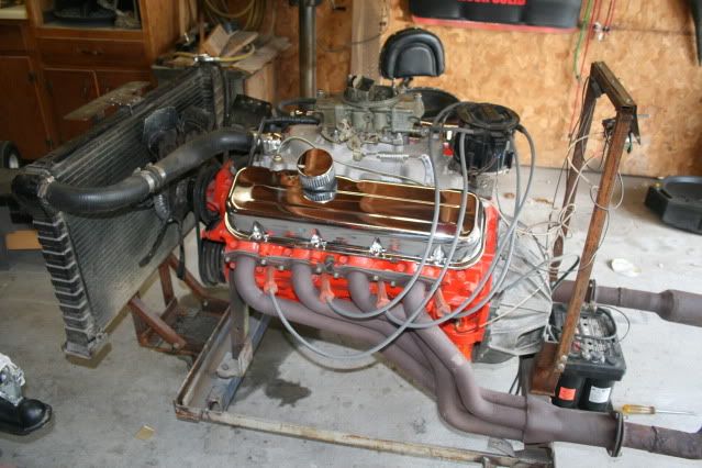
I've run my second motor on it, a Ford 302 stroker motor. In order to make it work, I had to add an MSD ignition and coil to the stand, which I did below the radiator on the "drivers" side. That was because I was using a magnetically triggered distributor that couldn't directly run a coil.
Here's what it looks like with this motor:
I found that the gauges work fine with this project. I had installed both mechanical and electrical oil pressure gauges on the instrument panel since I had an extra hole for expansion - this motor had an oil pressure "issue" and it was nice to have both gauges to be able to confirm proper operation of the gauge and sender. At the local Pull-A-Part I found a single top hose that worked, and was able to cut up and join four for the bottom hose. Lots of clamps, but inexplicably it doesn't leak.
I had put some extra caster pads in the middle of the stand, just in case I needed them. As it turns out, I didn't need them, and the middle pads are about where the front motor mount wants to be with this motor. I suppose I should have left the pads off. This is a high power motor though, and when you hit it, there is some flex in the stand.
One other minor change I would make. I wired it so that the gauges turned on with the ignition. Next time, I would have a separate switch for the gauges. This would allow you to leave the ignition off, but still turn over the motor and watch the oil pressure gauge as you prime the oil system prior to fire-up.
The stand saved a lot of work on this project. I had made an assembly error on this motor. So in addition to getting the motor tuned up and tested, it allowed me to find the problem and easily fix it prior to installing the motor in the car (and having to pull it again).
PS - this is a LOUD motor with little 12" long straight pipes. What little hearing I used to have must be even less now. Would be nice to have a muffler set-up. Better yet, also a way to run the exhaust outside the shop. Not that the entire stand can't be rolled outside.
LaineFamily home page...

#5
08-18-2009, 07:31 AM
Cool right up! As John mentioned, the pics aren't showing up. I can't wait to see them.
To help with the wild gauge fluctuations you might try twisiting the wires for each gauge together. GM used to do this on the injectors in the old throttle body injection systems to help reduce the chance of an induced voltage affecting the injector pulse rate.
There's something inherently cool about running and engine on a stand
Big thumbs up to you
Bobby
#6
08-18-2009, 08:02 AM
Join Date: Apr 2007
Location: Olympia Wa
Posts: 200
Likes: 0
Received 0 Likes
on
0 Posts
here is the web where i found it I thought some would be intreasted
http://www.lainefamily.com/EngineStandProject.htm
http://www.lainefamily.com/EngineStandProject.htm
#7
08-18-2009, 08:32 AM
Trending Topics
 [/IMG]
#9
08-18-2009, 02:05 PM
Logistics Pro
 Jag
Jag
#11
08-19-2009, 09:59 PM
These engine test stands are really handy. I threw this one together several years ago out of junk that I had laying around the shop. Nothing fancy, not even paint, but it works great. You find that you have a lot of extra friends that want that new engine tested before it goes in their new ride.
I'd like to build a nice one like flyin 51 built, but mounted on a small trailer.
Andrew
I'd like to build a nice one like flyin 51 built, but mounted on a small trailer.
Andrew
#12
08-19-2009, 10:11 PM
I have drawn up plans to do just that. Torsion spring wheels with the upright and working parts of the cherry picker mounted up by the tongue, and the testing parts surrounding the sides. Made to be pulled by an ATV, or riding lawn mower. Back up and straddle the engine, lift it, set the removeable crossmember in place, lower engine, bolt it to the crossmember, and hook the doo-dads up. Then you can pull it around the yard to wherever you want....in my case back into the engine shed. My goal was to use it for testing engines upon a purchase, and to keep engines in working order as they sit. But it could double as a final test before install as well.
Flyin 51's sure takes it up a notch, though.
Flyin 51's sure takes it up a notch, though.
#13
08-19-2009, 11:15 PM
Join Date: Apr 2007
Location: Olympia Wa
Posts: 200
Likes: 0
Received 0 Likes
on
0 Posts
#14
09-16-2009, 09:47 PM
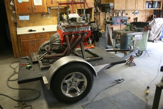
When Flyin 51 started this thread, I decided that now was the time to start on my trailer mounted engine test stand. I had enough stuff laying around the shop to put together the frame of the trailer. I picked up some 2" square tubing, and a few misc. trailer parts and threw together what you see here. I've still got a lot of details to fab up, but I've got most of the big stuff done. I guess stuff like this is why my 55 has been in the build stage for so long.
Now when one of the friends want their engines test run, I will be able take it to them instead of having to haul their engine to my shop and..... it might be an interesting conversation piece to pull to the local cruise -in.(perhaps behind my 55 someday)


Next I guess I've got to figure out how to put a hidden trailer hitch on my 55. Another new project!!!!.")
Andrew
Now when one of the friends want their engines test run, I will be able take it to them instead of having to haul their engine to my shop and..... it might be an interesting conversation piece to pull to the local cruise -in.(perhaps behind my 55 someday)
Next I guess I've got to figure out how to put a hidden trailer hitch on my 55. Another new project!!!!.
Andrew
