Can you tell me where these wires go?
#1
 07-22-2009, 07:18 AM

Join Date: Jun 2006
Posts: 654
Likes: 0
Received 0 Likes
on
0 Posts
Can you tell me where these wires go?
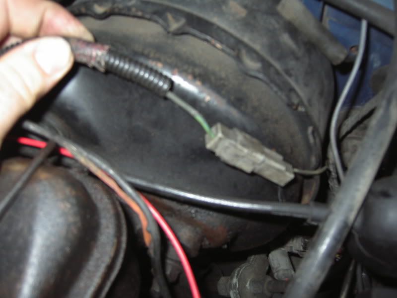
1985 F250 460/Auto w/ammeter I have a very bad wiring diagram, so I'd like some help. The ammeter doesn't work, and it's plainly unhooked. but I don't know how to hook it back up! I will segment this into a couple posts to break up the massive headache it is, I hope this is alright.
First Post, the 4 pin plug- (IF ANYONE CAN GET ME THIS HARNESS OR A PART NUMBER I WOULD LOVE TO BUY ONE)
Wire #1- Large Yellow Wire
I believe that the large yellow wire in the 4 pin plug is supposed to turn into a Black-Orange wire from the B+ terminal on the alternator. Right now, it's connected to the + terminal on the battery. I will correct this for the sake of correcting whatever I can find.
Wire #2 Lt Green - Red
Comes from the S terminal on the Voltage Regulator. Hooked up correctly.
Wire #3 Yellow - Lt Green
This wire comes out the the 4 pin, and goes no where. It is not on my wiring diagram. Where does yours go?
Wire #4 Red - Orange
This 1" wire appears on my diagram to go "To Ammeter" I believe the disconected side should be running to the B+ terminal on the alternator.
[IMG]<a href="http://s97.photobucket.com/albums/l202/RoastGecko/Truck%20Wiring/?action=view¤t=EPSN0026.jpg" target="_blank"><img src="http://i97.photobucket.com/albums/l202/RoastGecko/Truck%20Wiring/EPSN0026.jpg" border="0" alt="The 4 Pin harness"></a>[/IMG]
#2
07-22-2009, 07:42 AM
Join Date: Jun 2006
Posts: 654
Likes: 0
Received 0 Likes
on
0 Posts
Post #2- Alternator
3 Wires
Wire #1 Red Bat +
This wire runs directly to the hot side of the starter relay. I will instead be running this directly to the heavy yellow wire from the last post, in effect replaceing the "Black-Orange" wire that was factory. I will also hook the little Red-Orange wire from post 1 here as well.
Wire #2 Orange-Lt Blue Field
This wire runs from the F terminal on the alternator to the F terminal on the Voltage Regulator. It appears to be correct.
Wire #3 Orange-ish Stator (shown in pics)
The wiring diagram says it should be White-Black and it should run to the Choke Heater. Mine Runs into a blue plug, that has a single Green - Yellow wire that runs across the engine in a shroud, and plugs into the harness again near the brake booster. I lose track here, but it doesn't seem to run to my electric choke. (my choke wasn't hooked up when I bought it. It's now wired to a switched 12v source)
<a href="http://s97.photobucket.com/albums/l202/RoastGecko/Truck%20Wiring/?action=view¤t=EPSN0014.jpg" target="_blank"><img src="http://i97.photobucket.com/albums/l202/RoastGecko/Truck%20Wiring/EPSN0014.jpg" border="0" alt="Alternator"></a>
<a href="http://s97.photobucket.com/albums/l202/RoastGecko/Truck%20Wiring/?action=view¤t=statorline.jpg" target="_blank"><img src="http://i97.photobucket.com/albums/l202/RoastGecko/Truck%20Wiring/statorline.jpg" border="0" alt="Supposed Choke Heater line"></a>
#3
07-22-2009, 07:55 AM
Join Date: Jun 2006
Posts: 654
Likes: 0
Received 0 Likes
on
0 Posts
Last post- Things I learned writing this-
All my problems may be related-
I have a circuit the "Courtesy Light" fuse that only has power when running if the fuse is blown, which seems to happen frequently. My other crappy wiring diagram shows that this fuse has a line to the "Alternator Voltage Regulator"
I'm wondering if this line from the fuse panel is supposed to run to the regulator as this diagram says, but is instead running to the stator line, which the diagram says should be running my choke?
Does the Stator terminal on the alternator have voltage only when running, or is that the field terminal?
#4
07-22-2009, 08:01 AM

Orange-ish Stator (shown in pics)
The wiring diagram says it should be White-Black and it should run to the Choke Heater. Mine Runs into a blue plug, that has a single Green - Yellow wire that runs across the engine in a shroud, and plugs into the harness again near the brake booster. I lose track here, but it doesn't seem to run to my electric choke. (my choke wasn't hooked up when I bought it. It's now wired to a switched 12v source)
The wiring diagram says it should be White-Black and it should run to the Choke Heater. Mine Runs into a blue plug, that has a single Green - Yellow wire that runs across the engine in a shroud, and plugs into the harness again near the brake booster. I lose track here, but it doesn't seem to run to my electric choke. (my choke wasn't hooked up when I bought it. It's now wired to a switched 12v source)

That LG/Y wire is the always-on circuit, used for things like a radio/clock
memory, courtesy lamps, underhood lamps, etc.
#5
07-22-2009, 08:24 AM
Join Date: Jun 2006
Posts: 654
Likes: 0
Received 0 Likes
on
0 Posts
And is it supposed to go to my Stator terminal on the alternator?
All the stuff you mentioned is right now working only when the engine is running, because the fuse is blown. I keep blowing fuses and haven't figured out why yet. I'm going to remove my radio, I'm pretty sure thats the problem. I'll have a new fuse in in a few minutes.
Any idea on the rest of them :0
#6
07-22-2009, 05:29 PM

Post Fiend
Join Date: Jul 2004
Location: Northern California
Posts: 8,786
Likes: 0
Received 18 Likes
on
17 Posts
Absolutely NOT. Remove that wire from the stator terminal of the altenator imediately. 
That is the plug for the underhood Retractable Courtesy Lamp option. (No wonder you are blowing fuses)
God the wiring of this thing is a mess, and a huge fire hazard. I'd park it and remove the battery Negative cable, before it ignites and burns. It looks like your fuse links are bypassed.
It looks like you are looking at the very least a partial re-wire job. I'll try and help you through it.
I've got the factory diagram, so it wont be hard. Just might be time consuming.
First thing I'd do, after parking and disconnecting the battery, is go to the wrecking yard and find another altenator wiring harness for a truck with gauges. I wouldn't even attempt fixing the old one.
That is the plug for the underhood Retractable Courtesy Lamp option. (No wonder you are blowing fuses)
All the stuff you mentioned is right now working only when the engine is running, because the fuse is blown. I keep blowing fuses and haven't figured out why yet. I'm going to remove my radio, I'm pretty sure thats the problem. I'll have a new fuse in in a few minutes.
It looks like you are looking at the very least a partial re-wire job. I'll try and help you through it.
I've got the factory diagram, so it wont be hard. Just might be time consuming.
First thing I'd do, after parking and disconnecting the battery, is go to the wrecking yard and find another altenator wiring harness for a truck with gauges. I wouldn't even attempt fixing the old one.
#7
07-22-2009, 06:10 PM

1985 F250 with all gauges (not idiot lights): There are SIX different "Alternator to Voltage Regulator" wiring harnesses. I kid you not.
It depends on what amperage the alternator is: 40-60, or 70.
It also depends on the production date: Before 11/84, or from 11/84.
The production date will be found on the upper left of the Certification Label located on the door post.
When the info is known, I'll type the Ford part number, see if anyone has it and post what I find.
btw: As original, there was a white paper tag glued to the harness with a Ford ID number on it.
If that's still there, post what the ID number is: It'll be something like this: E5TE-14305-AA
Trending Topics
#8
07-23-2009, 02:14 AM
Join Date: Jun 2006
Posts: 654
Likes: 0
Received 0 Likes
on
0 Posts
Absolutely NOT. Remove that wire from the stator terminal of the altenator imediately.
That is the plug for the underhood Retractable Courtesy Lamp option. (No wonder you are blowing fuses)
God the wiring of this thing is a mess, and a huge fire hazard. I'd park it and remove the battery Negative cable, before it ignites and burns. It looks like your fuse links are bypassed.
It looks like you are looking at the very least a partial re-wire job. I'll try and help you through it.
I've got the factory diagram, so it wont be hard. Just might be time consuming.
First thing I'd do, after parking and disconnecting the battery, is go to the wrecking yard and find another altenator wiring harness for a truck with gauges. I wouldn't even attempt fixing the old one.
That is the plug for the underhood Retractable Courtesy Lamp option. (No wonder you are blowing fuses)
God the wiring of this thing is a mess, and a huge fire hazard. I'd park it and remove the battery Negative cable, before it ignites and burns. It looks like your fuse links are bypassed.
It looks like you are looking at the very least a partial re-wire job. I'll try and help you through it.
I've got the factory diagram, so it wont be hard. Just might be time consuming.
First thing I'd do, after parking and disconnecting the battery, is go to the wrecking yard and find another altenator wiring harness for a truck with gauges. I wouldn't even attempt fixing the old one.
I went down to the Ford dealer today, and dug through a old wiring diagram. I would have never figured it out on my own. The yellow/ white wire from the A terminal on the regulator runs to the ammeter by way of the red/orange wire in the 4 pin plug (C 201 or C 202 in the factory wiring diagram if you want to verify this for me) and the yellow/green wire should be combined with the B+ output from the alternator. (Again, C 201 or C 202) I might be remembering it wrong, but I have it written down.
That wire is running to the stator is really the only wild card now.
#9
07-23-2009, 02:17 AM
Join Date: Jun 2006
Posts: 654
Likes: 0
Received 0 Likes
on
0 Posts
1985 F250 with all gauges (not idiot lights): There are SIX different "Alternator to Voltage Regulator" wiring harnesses. I kid you not.
It depends on what amperage the alternator is: 40-60, or 70.
It also depends on the production date: Before 11/84, or from 11/84.
The production date will be found on the upper left of the Certification Label located on the door post.
When the info is known, I'll type the Ford part number, see if anyone has it and post what I find.
btw: As original, there was a white paper tag glued to the harness with a Ford ID number on it.
If that's still there, post what the ID number is: It'll be something like this: E5TE-14305-AA
It depends on what amperage the alternator is: 40-60, or 70.
It also depends on the production date: Before 11/84, or from 11/84.
The production date will be found on the upper left of the Certification Label located on the door post.
When the info is known, I'll type the Ford part number, see if anyone has it and post what I find.
btw: As original, there was a white paper tag glued to the harness with a Ford ID number on it.
If that's still there, post what the ID number is: It'll be something like this: E5TE-14305-AA
#10
07-23-2009, 03:18 AM
40-60 Amp / From 11/84 / Use with Oil & Amp Gauges.
Fits: 1985 F150/350 & Bronco.
GREEN SALES CO. in Cincinnati OH has TWO = 800-543-4959.
No Ford Dealer, no other obsolete parts vendor has any.
==========================================
The 70 amp alternator harness used with gauges (E3TZ14305D) is the same 1983/85.
No Ford Dealer or obsolete parts vendor has any.
#11
07-23-2009, 04:36 AM
Post Fiend
Join Date: Jul 2004
Location: Northern California
Posts: 8,786
Likes: 0
Received 18 Likes
on
17 Posts
You said it was here...
Wire #1- Large Yellow Wire
I believe that the large yellow wire in the 4 pin plug is supposed to turn into a Black-Orange wire from the B+ terminal on the alternator. Right now, it's connected to the + terminal on the battery.
With it hooked like the above, you are bypassing at least one Fuse link. The one off the Starter Solenoid.
Also be aware that there are more than 1 Black/Orange wires.
The Yellow wire connects the two Black/Orange wires together, via a Orange Fuse Link. One black/Orange wire feeds the Fuse Panel and Headlamp switch, and the other goes to the B terminal on the altenator. Don't mix them up.
And the worring thing is you have wires hooked up incorrectly. As quoted by you above.
The wiring diagrams I have tell me what component the a wire goes to (ie "ammeter") but not how it gets there. And that black tape job is actually kind of correct, just funny looking. The thick Yellow wire, should be combined with the B+ wire from the alt, so it is Hot as it is now, .
Correct, but the placement on the Black/Orange wire is crutial for safe operation.
This is incorrect. Yellow/White comes from the Black/Orange wire and goes to the altenator regulator A terminal.
I doubt they used one with a mess like you have, I'm sorry to say. Very sloppy and dangerous mistakes were made.
It's not a connector, they are splices. (S-201 and S-202). And the Yellow/White wire does not go to the ammeter. It splices into the Black/orange wire that connects to the fuse link that connects to your starter solenoid. The Red/Orange wire that goes to the ammeter, splices into the Black/Orange wire at the same splice as the Yellow/White wire. (S-201)
It connects to The same Black/Orange wire, but at splice (S-202). This is where the yellow wire also splices into the Black/Orange wire.
Be aware and a word of warning. The black/orange wire between splices (S-201) and (S-202) is the ammeter shunt. Without this shunt, the ammeter in the cab can catch fire. The ammeter is not designed to take the full charging amps of the altenator. It's only designed for 1.5 amps. Without the shunt the ammeter will overload and burn.
The only thing that should be hooked to your stator, is the White/Black stripe wire. This goes to your Electric Choke. Do not have anything else hooked to the stator. Especially not your courtesy lamp circut as it was.
The wiring should be hooked up as follows...
1: From the Starter Solenoid Battery LUG, (C-213) there is a fuseable link attached (#291 BK (black)).
2: From there it goes to splice (S-219) where it changes into a Black/Orange stripe wire (#38 BK-O).
3: (#38 BK-O) continues to another splice (S-201) where 2 wires, connect to (#38 BK-O).
4: The two wires spliced into (#38 BK-O) at (S-201) are (#36 Y-W) Yellow/White stripe and (#655 R-O) Red/Orange stripe.
5: (#36 Y-W) goes to the Voltage Regulator. (#655 R-O) goes to the D side of the Ammeter.
6: (#38 BK-O) continues from (S-201) and turns into a Ammeter Shunt between splices (S-201) and (S-202).
7: At splice (S-202) 2 more wires converge. (#654 Y-LG) and (#37 Y).
8: (#654 Y-LG) Yellow/Light Green goes to the C side of the ammeter.
9: (#37 Y) Yellow, goes to Connector C-610, where it continues to S-211 where 2 fuse links are hooked to S-211. Orange and Dark Green.
10: The Orange fuse link connects (#37 Y) and another seperate (#38 BK-O) wire that supplies the Headlamp Switch and fuse panels hot at all time circuts. Do not confuse this with the altenator wire of the same color.
11: The Dark Green Fuse link connects to another (#37 Y) wire that supplies the ignition switch. Don't confuse this yellow wire with the first one.
12: (#38 BK-O) continues from (S-202) as a regular wire, goes to the Altenator B terminal.
You really need to get a new harness. And as I said, I wouldn't drive it untill you do, or leave the battery connected, untill it's repaired. The truck could be a potential fire hazard, and with at least one of the fuse links bypassed, you have no protection if a catastrophic failure occurs.
Wire #1- Large Yellow Wire
I believe that the large yellow wire in the 4 pin plug is supposed to turn into a Black-Orange wire from the B+ terminal on the alternator. Right now, it's connected to the + terminal on the battery.
Also be aware that there are more than 1 Black/Orange wires.
The Yellow wire connects the two Black/Orange wires together, via a Orange Fuse Link. One black/Orange wire feeds the Fuse Panel and Headlamp switch, and the other goes to the B terminal on the altenator. Don't mix them up.
Sure, the solder mess under the black tape is a ****ty job, but thats the worst of it. I'm 99% sure that all the unhooked wires are for the ammeter now.
The wiring diagrams I have tell me what component the a wire goes to (ie "ammeter") but not how it gets there. And that black tape job is actually kind of correct, just funny looking. The thick Yellow wire, should be combined with the B+ wire from the alt, so it is Hot as it is now, .
and the Yellow/white wire that plugs in via that blue crimp is supposed to run to my ammeter, but should be run to hot on a truck that didn't have the ammeter.
So is looks like they must have had the wrong wiring diagram, and didn't know it.
I went down to the Ford dealer today, and dug through a old wiring diagram. I would have never figured it out on my own. The yellow/ white wire from the A terminal on the regulator runs to the ammeter by way of the red/orange wire in the 4 pin plug (C 201 or C 202 in the factory wiring diagram if you want to verify this for me)
and the yellow/green wire should be combined with the B+ output from the alternator. (Again, C 201 or C 202) I might be remembering it wrong, but I have it written down.
Be aware and a word of warning. The black/orange wire between splices (S-201) and (S-202) is the ammeter shunt. Without this shunt, the ammeter in the cab can catch fire. The ammeter is not designed to take the full charging amps of the altenator. It's only designed for 1.5 amps. Without the shunt the ammeter will overload and burn.
That wire is running to the stator is really the only wild card now.
The wiring should be hooked up as follows...
1: From the Starter Solenoid Battery LUG, (C-213) there is a fuseable link attached (#291 BK (black)).
2: From there it goes to splice (S-219) where it changes into a Black/Orange stripe wire (#38 BK-O).
3: (#38 BK-O) continues to another splice (S-201) where 2 wires, connect to (#38 BK-O).
4: The two wires spliced into (#38 BK-O) at (S-201) are (#36 Y-W) Yellow/White stripe and (#655 R-O) Red/Orange stripe.
5: (#36 Y-W) goes to the Voltage Regulator. (#655 R-O) goes to the D side of the Ammeter.
6: (#38 BK-O) continues from (S-201) and turns into a Ammeter Shunt between splices (S-201) and (S-202).
7: At splice (S-202) 2 more wires converge. (#654 Y-LG) and (#37 Y).
8: (#654 Y-LG) Yellow/Light Green goes to the C side of the ammeter.
9: (#37 Y) Yellow, goes to Connector C-610, where it continues to S-211 where 2 fuse links are hooked to S-211. Orange and Dark Green.
10: The Orange fuse link connects (#37 Y) and another seperate (#38 BK-O) wire that supplies the Headlamp Switch and fuse panels hot at all time circuts. Do not confuse this with the altenator wire of the same color.
11: The Dark Green Fuse link connects to another (#37 Y) wire that supplies the ignition switch. Don't confuse this yellow wire with the first one.
12: (#38 BK-O) continues from (S-202) as a regular wire, goes to the Altenator B terminal.
You really need to get a new harness. And as I said, I wouldn't drive it untill you do, or leave the battery connected, untill it's repaired. The truck could be a potential fire hazard, and with at least one of the fuse links bypassed, you have no protection if a catastrophic failure occurs.
#12
03-21-2010, 06:38 PM
Join Date: Jun 2006
Posts: 654
Likes: 0
Received 0 Likes
on
0 Posts
I can't believe I never posted here again!
I wanted to thank you all for your help. I haven't fixed everything yet, but with your help I identified all the wires, where they should go, and what was done wrong. I'm planning to buy the correct harness as soon as I have the obscene amount they want for it.
I now have my electric choke hooked up properly, my clock and radio work fine, and all extraneous wiring has been covered and a fuse was put in line with the alternator.
I've made massive progress on my truck, and hope to be driving it again in a few weeks. The biggest headache was wiring stuff, so again THANK YOU ALL SO MUCH.

Thread
Thread Starter
Forum
Replies
Last Post
SparkyRnD
1973 - 1979 F-100 & Larger F-Series Trucks
10
09-23-2019 10:04 PM
mgerdau
1948 - 1956 F1, F100 & Larger F-Series Trucks
6
05-28-2016 11:17 PM
97Fordf35089f250
1987 - 1996 F150 & Larger F-Series Trucks
20
12-31-2015 12:25 AM
KWittmer
1973 - 1979 F-100 & Larger F-Series Trucks
3
12-05-2010 01:25 PM