CC help
#1
 06-15-2009, 07:46 AM


#2
06-15-2009, 08:48 AM

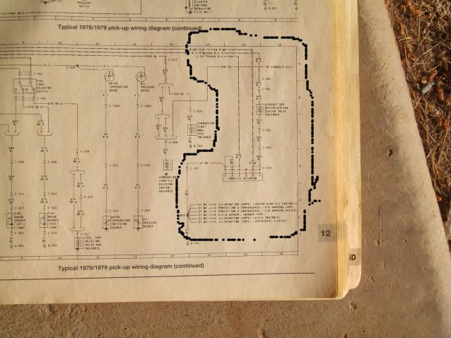
I don't see these color wires in the system. In the left portion of this picture should be the speedo cable. If you have cruise, your cable from the speedo head should be very short, and barely it make it through the firewall, and it should plug into a little round pot metal piece with wires coming out of it. This is the speed sensor for the cruise. Then a longer cable continues out of this sensor down to the tranny.
You should have a darkgreen/white and a black connected to this sensor. You should also have a servo hooked to the throttle with 6 wires coming out of it. Both sets of wires should run through the firewall and go to a control box mounted under the dash. There will be one other wire going to the steering column for the controls, one for power, and one going to the brake light switch.
You should have a darkgreen/white and a black connected to this sensor. You should also have a servo hooked to the throttle with 6 wires coming out of it. Both sets of wires should run through the firewall and go to a control box mounted under the dash. There will be one other wire going to the steering column for the controls, one for power, and one going to the brake light switch.
#3
06-15-2009, 08:21 PM
Everything is there like you said.Maybe this(pic) is throwing me off? I guess I should be asking"How do I trouble shoot the CC system?"
Also have trouble with these guys,but I just bypassed them and used a coil wire to get it up to the horn pad.Any other trouble shooting tricks I can do? Thanks for the help.Just trying to get it working again.
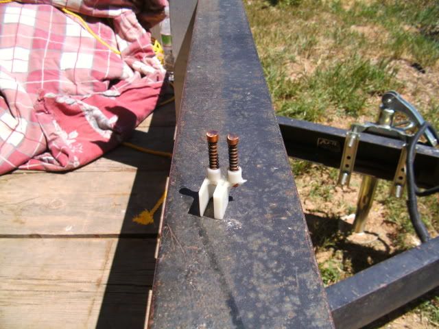
Yea two switches for the brake,one kind of on the rod/pedel and the other one on the pedel.
Also have trouble with these guys,but I just bypassed them and used a coil wire to get it up to the horn pad.Any other trouble shooting tricks I can do? Thanks for the help.Just trying to get it working again.
Yea two switches for the brake,one kind of on the rod/pedel and the other one on the pedel.
#4
06-15-2009, 09:30 PM

#5
06-15-2009, 10:16 PM
#6
06-16-2009, 08:48 AM
#7
06-16-2009, 10:49 AM
Trending Topics
#11
06-20-2009, 01:02 PM
The top mech switch is ON,bottom switch(brake?) is off with the pedel in the upright positionTo top goes OFF and the bottom goes ON when the pedel is pressed.
Is this right?
I am trying to test the ON switch to the connector at the Amp(hit ON and should see something at the meter).I have a good idea what wire it is(I think),BK/GRAY.Can you tell me what that color it is? 79 f250 460-c6
Is this right?
I am trying to test the ON switch to the connector at the Amp(hit ON and should see something at the meter).I have a good idea what wire it is(I think),BK/GRAY.Can you tell me what that color it is? 79 f250 460-c6
#12
06-20-2009, 01:31 PM

