Updated harness connectors
#1
 04-05-2009, 08:47 AM

Updated harness connectors
I posted this over on the HAMB. I though you might enjoy it too.
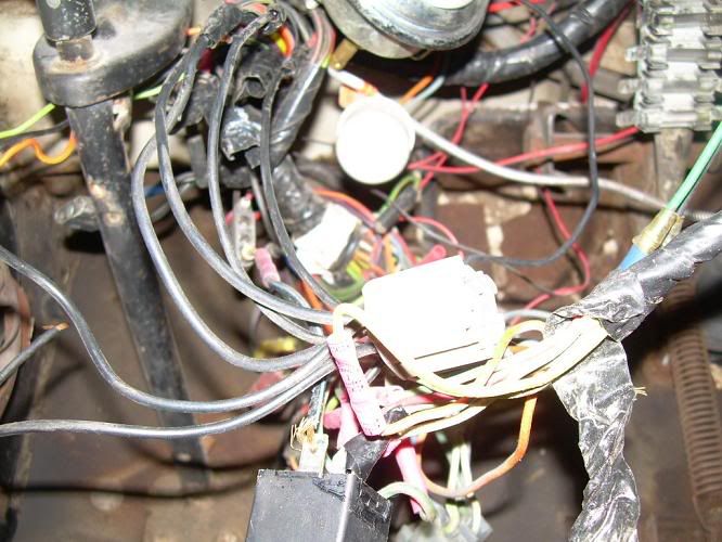
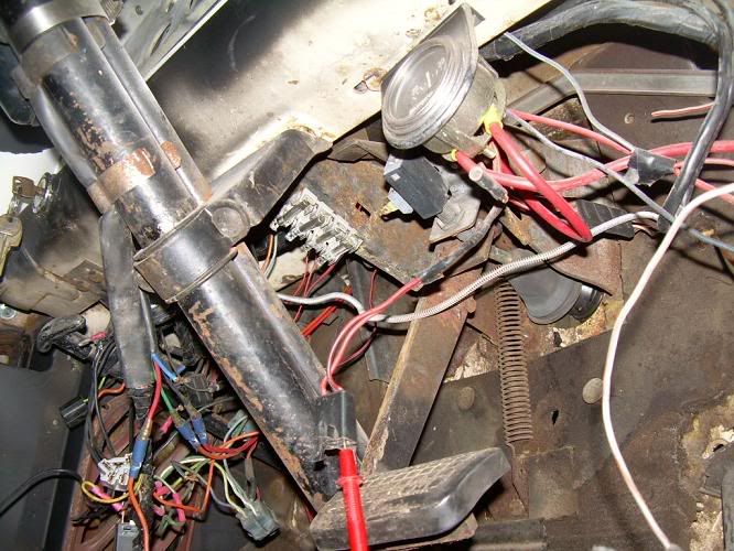
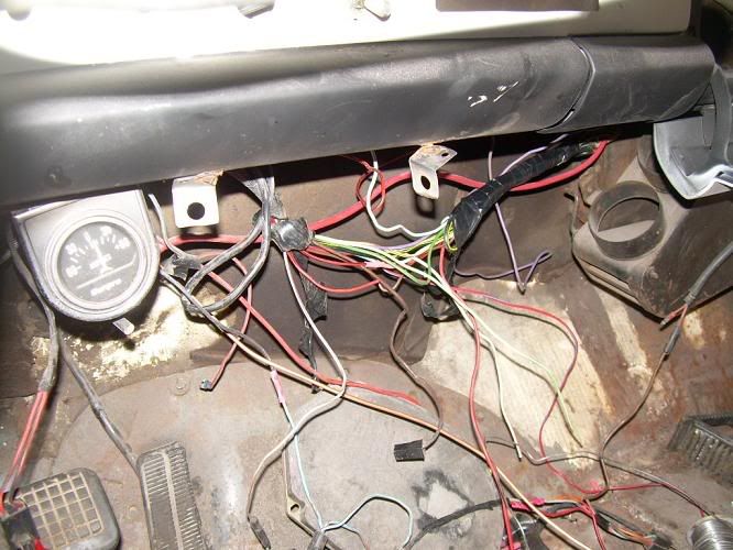
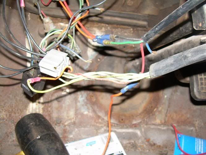
I've recently pulled my 58 F100 out of hybernation to finish work that I started years ago. One of the bigger issues is the wiring. When I first bought the truck, a previous owner had fried the harness behind the cluster somehow. Instead of fixing the problem, they just spliced into the burnt wiring and routed it around the burnt part. You could start the engine with the key, but had to pull the coil wire to kill the motor. I had a 68 F100 that I was about to scrap, so I pulled the harness and all of the switches out of it, and installed them in my 58. I know that a forty year old harness is not a lot better than a 50 year old harness, but considering what I started with, and the fact that I couldn't afford a new harness at the time. I went with what I had. The 68 is considerably wider than the 58 in regards to wire length, and I didn't alter it in any way, so when I installed it, I had bunches of wire hanging from the dash that looked horrible. I have no one to blame but myself for the conditon of the harness in the following pics. I am now in the process of correcting this.

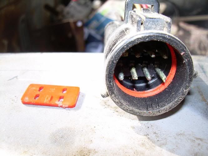
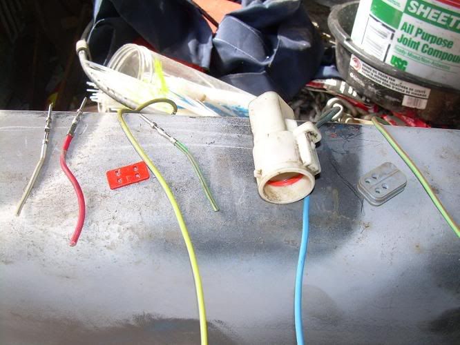
To start off, I went to the local pick N pull. I was able to find a rolled 96 F150 and get a five gallon bucket full of connectors like these for 15 bucks.
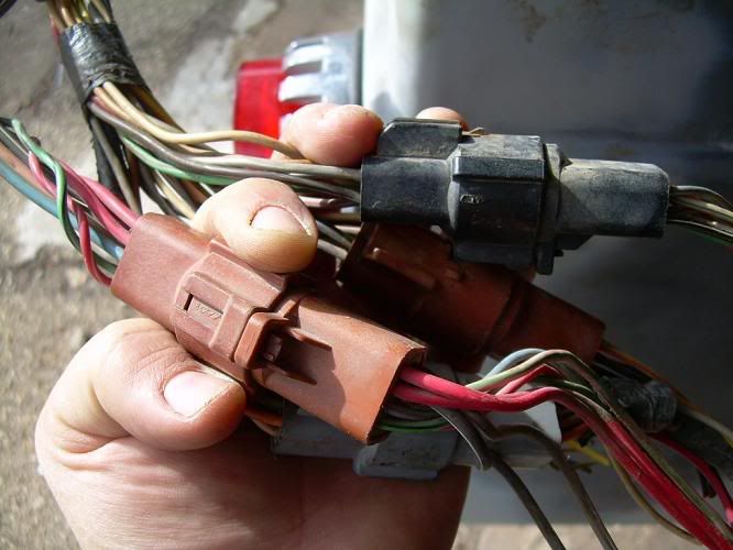
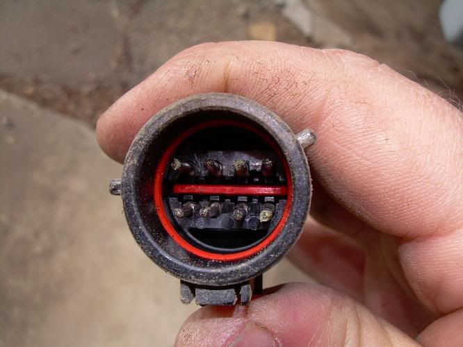
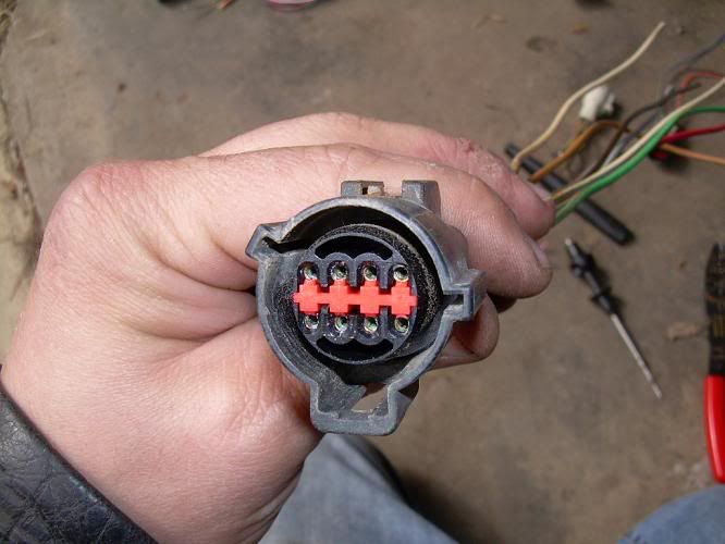
These connectors are a male/female plastic housing with multiple male/female pin connectors inside.
To start, I looked up the diagram for the signal switch on my stock column.
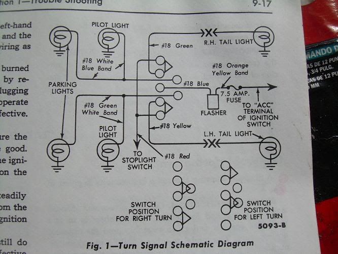
According to the diagram, I needed six wire connectors. A red, a blue, a white with blue tracer, a yellow, a green, and a green with white tracer. I dug through the pile of connectors I had, and was able to find a red, a blue, a white with blue tracer, a yellow with blue tracer, a green with red tracer, and a green with orange tracer. If I had thought to look while at the pick n pull, I probably could have found exactly what I needed in regards to wire color, but this will do.
The connectors are assembled in a way that the wires snap in from the back, with a small insert to keep them from accidentally coming loose. When the correct wire is located. Remove the plastic insert from the connector. I am using a bicycle spoke bent in a way to get to the insert without really damaging anything.
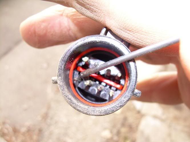
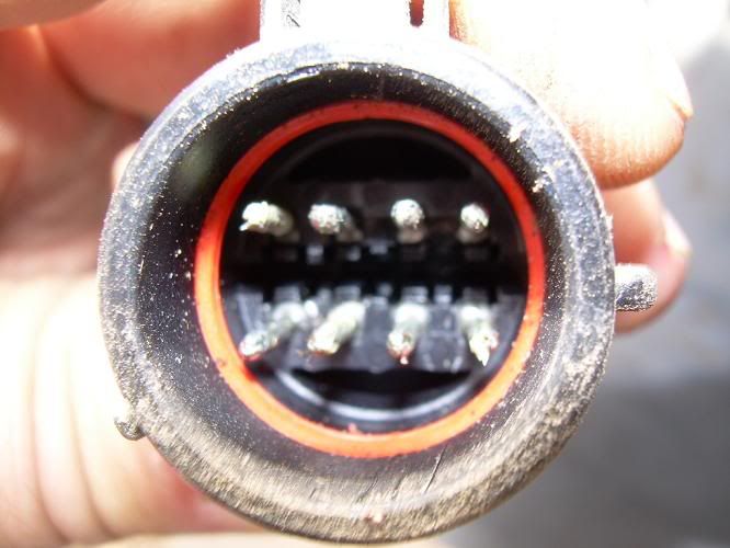
With the insert removed, you can see the locks that keep the wires in.
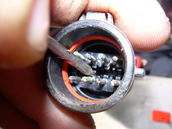
Using a small probe, this is the end of a broken circuit tester, I carefully pried back the lock, and pulled the wire out from the back of the connector.
When all of the wires I needed were found and removed, I was ready to start reassembling the connector to fit my application.
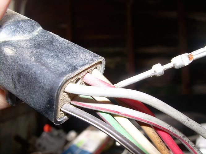
I found each of the six wires referenced in the wiring diagram, and clipped them off at different lengths so that when I made all of the new connections, there wouldn't be a big bulge in my harness.
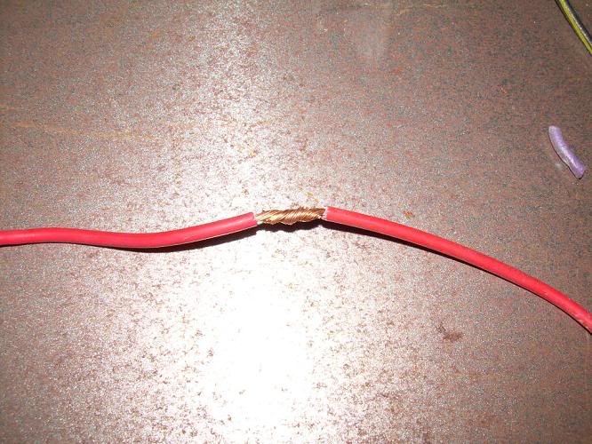
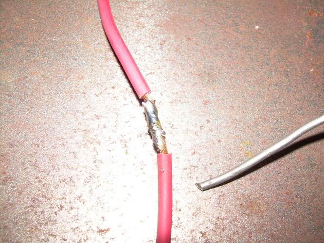
I didn't fully think it out before I started cutting and cut the red wire the shortest. I should have made it one of the longer wires, because the end I was soldering on was one of the shortest. I had to lengthen the red wire now, so I took the time to show you how to make a good connection. When splicing two wires together, the splice should look like this before soldering.
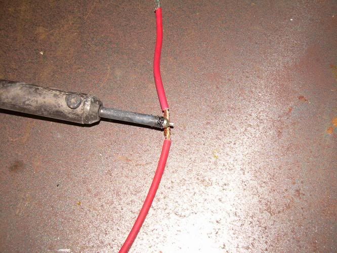
Heat the connection up with the tip of the iron and apply solder to the hot connection.
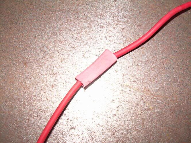
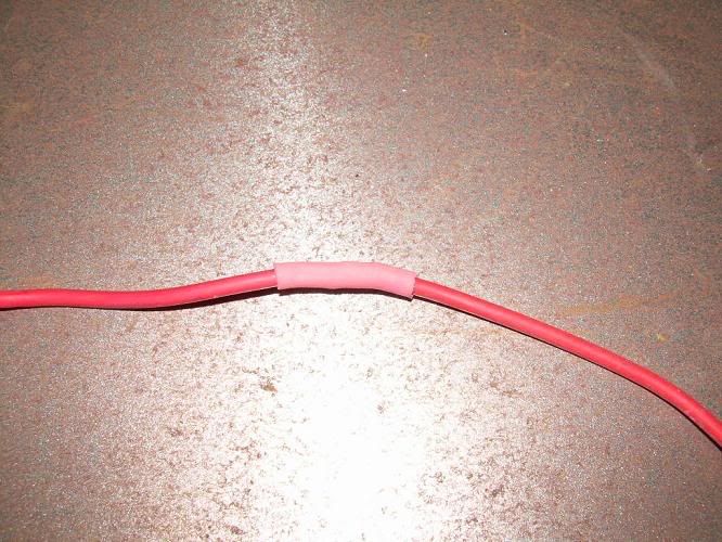
Cover the soldered splice with heat shrink tubing and apply heat.
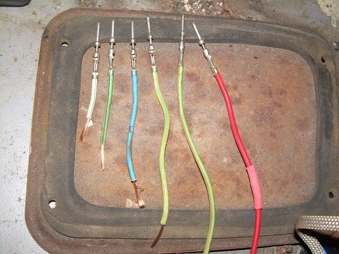
Because the wires from the signal switch were cut to different lengths, the wires being soldered on needed to be cut to lengths to match.
I've recently pulled my 58 F100 out of hybernation to finish work that I started years ago. One of the bigger issues is the wiring. When I first bought the truck, a previous owner had fried the harness behind the cluster somehow. Instead of fixing the problem, they just spliced into the burnt wiring and routed it around the burnt part. You could start the engine with the key, but had to pull the coil wire to kill the motor. I had a 68 F100 that I was about to scrap, so I pulled the harness and all of the switches out of it, and installed them in my 58. I know that a forty year old harness is not a lot better than a 50 year old harness, but considering what I started with, and the fact that I couldn't afford a new harness at the time. I went with what I had. The 68 is considerably wider than the 58 in regards to wire length, and I didn't alter it in any way, so when I installed it, I had bunches of wire hanging from the dash that looked horrible. I have no one to blame but myself for the conditon of the harness in the following pics. I am now in the process of correcting this.
To start off, I went to the local pick N pull. I was able to find a rolled 96 F150 and get a five gallon bucket full of connectors like these for 15 bucks.
These connectors are a male/female plastic housing with multiple male/female pin connectors inside.
To start, I looked up the diagram for the signal switch on my stock column.
According to the diagram, I needed six wire connectors. A red, a blue, a white with blue tracer, a yellow, a green, and a green with white tracer. I dug through the pile of connectors I had, and was able to find a red, a blue, a white with blue tracer, a yellow with blue tracer, a green with red tracer, and a green with orange tracer. If I had thought to look while at the pick n pull, I probably could have found exactly what I needed in regards to wire color, but this will do.
The connectors are assembled in a way that the wires snap in from the back, with a small insert to keep them from accidentally coming loose. When the correct wire is located. Remove the plastic insert from the connector. I am using a bicycle spoke bent in a way to get to the insert without really damaging anything.
With the insert removed, you can see the locks that keep the wires in.
Using a small probe, this is the end of a broken circuit tester, I carefully pried back the lock, and pulled the wire out from the back of the connector.
When all of the wires I needed were found and removed, I was ready to start reassembling the connector to fit my application.
I found each of the six wires referenced in the wiring diagram, and clipped them off at different lengths so that when I made all of the new connections, there wouldn't be a big bulge in my harness.
I didn't fully think it out before I started cutting and cut the red wire the shortest. I should have made it one of the longer wires, because the end I was soldering on was one of the shortest. I had to lengthen the red wire now, so I took the time to show you how to make a good connection. When splicing two wires together, the splice should look like this before soldering.
Heat the connection up with the tip of the iron and apply solder to the hot connection.
Cover the soldered splice with heat shrink tubing and apply heat.
Because the wires from the signal switch were cut to different lengths, the wires being soldered on needed to be cut to lengths to match.
#2
04-05-2009, 09:28 AM
Cargo Master
#3
04-05-2009, 11:40 AM

Post Fiend
I feel your pain too- every time I read a post about adapting used old wiring to put in a truck.
Guys, I'm not trying to be a pill or insulting here. But I just do not understand why people feel they need to have a "Harness" to install in the trucks to make it electrically sound. And I especially don't understand why they want to pull that massive tracing nightmare of wires out of something old and try to adapt it to a different vehicle.
That's just incorporating problems right off the bat and that's what makes rewiring difficult.
Take a word of sincerely offered advice - throw the harnesses away and rewire one wire at a time from point to point, then bundle your wires into a harness (since you feel the need for harnesses) when you are finished. It's cleaner, it's safer, and it works better.
Connecting the dots - one by one, rather than untangling and taming an octopus of wires, will make the job a breeze.
I have generic diagrams in my #1 and #2 galleries - I will be happy to send the whole package to all of you. They are MS Power Point so you can customize them for your own truck, and end up with the wiring diagram that is specific to it. Send me a PM with your real e-mail addres if you would like me to send you the files.
#4
04-05-2009, 12:26 PM
I feel your pain too- every time I read a post about adapting used old wiring to put in a truck.
Guys, I'm not trying to be a pill or insulting here. But I just do not understand why people feel they need to have a "Harness" to install in the trucks to make it electrically sound. And I especially don't understand why they want to pull that massive tracing nightmare of wires out of something old and try to adapt it to a different vehicle.
That's just incorporating problems right off the bat and that's what makes rewiring difficult.
Take a word of sincerely offered advice - throw the harnesses away and rewire one wire at a time from point to point, then bundle your wires into a harness (since you feel the need for harnesses) when you are finished. It's cleaner, it's safer, and it works better.
Connecting the dots - one by one, rather than untangling and taming an octopus of wires, will make the job a breeze.
I have generic diagrams in my #1 and #2 galleries - I will be happy to send the whole package to all of you. They are MS Power Point so you can customize them for your own truck, and end up with the wiring diagram that is specific to it. Send me a PM with your real e-mail addres if you would like me to send you the files.
Guys, I'm not trying to be a pill or insulting here. But I just do not understand why people feel they need to have a "Harness" to install in the trucks to make it electrically sound. And I especially don't understand why they want to pull that massive tracing nightmare of wires out of something old and try to adapt it to a different vehicle.
That's just incorporating problems right off the bat and that's what makes rewiring difficult.
Take a word of sincerely offered advice - throw the harnesses away and rewire one wire at a time from point to point, then bundle your wires into a harness (since you feel the need for harnesses) when you are finished. It's cleaner, it's safer, and it works better.
Connecting the dots - one by one, rather than untangling and taming an octopus of wires, will make the job a breeze.
I have generic diagrams in my #1 and #2 galleries - I will be happy to send the whole package to all of you. They are MS Power Point so you can customize them for your own truck, and end up with the wiring diagram that is specific to it. Send me a PM with your real e-mail addres if you would like me to send you the files.
#5
04-05-2009, 12:28 PM
#6
04-05-2009, 12:39 PM
Elder User
Join Date: May 2006
Location: Kansas City, Mo
Posts: 907
Likes: 0
Received 0 Likes
on
0 Posts
Wiring
Great work.
Two options: If you don't want to splice, take your connectors to the dealer and buy replacement pins. They may have them in stock or maybe order them. It's been a while, so now they may require buying a complete connector. I have bent the pin's crimp end over a small nail to make a hole to solder my wire. If you live near a military parts surplus store, many of the older connectors are of the solder type and screw together.
When soldering a splice, I use a crimp splice, cut off the plastic cover and solder the wires in the metal splice. It takes less heat on each end than trying to heat a twisted set of wires and has a better penetrations of solder. The size is the same, and then I use the same heat shield as the twisted wire uses. You can solder the connector ends of the splice on the bench and take to the truck half done. I pre-solder the splice ends and metal splice separately, then place heat gun on the splice end and slide the pre-soldered wire in as you see the solder melt. This uses a minimum amount of heat time and less waste of solder. After one or two times you can judge the amount of solder to presolder wires and metal splice to keep a neat look to your work.
I down loaded iespell and I must be dumber than a door **** as I can't make it work. When it arrives at enter id I don't know what to enter on the file page, help!!!!!!!!!!!!!!!!!! chuck
#7
04-05-2009, 01:08 PM
When soldering a splice, I use a crimp splice, cut off the plastic cover and solder the wires in the metal splice. It takes less heat on each end than trying to heat a twisted set of wires and has a better penetrations of solder. The size is the same, and then I use the same heat shield as the twisted wire uses. You can solder the connector ends of the splice on the bench and take to the truck half done. I pre-solder the splice ends and metal splice separately, then place heat gun on the splice end and slide the pre-soldered wire in as you see the solder melt. This uses a minimum amount of heat time and less waste of solder. After one or two times you can judge the amount of solder to presolder wires and metal splice to keep a neat look to your work. chuck
Trending Topics
#8
04-05-2009, 03:19 PM
I'm pretty sure I get what you're saying, I'm going to try it out. It seems like it would work great. Soldering those connections on my back with the soldering iron in one hand, and the solder and wire in the other trying to make sure the connection was properly soldered was a real pain. Thanks!
#9
04-05-2009, 03:44 PM
Fleet Owner
Wiring is an art form. I gave up on making it a pretty job a long time ago, and just worry about making it bulletproof.
Yep, he's talking about the "butt connectors" with red/blue/yellow plastic over them. If you cut the exposed part with snips, and sort of peel them around on top of themselves, they'll come right off. They do sell them plain too, (no cover), at Home Depot.
The hardest part of wiring is remembering to put the heat shrink on the wire BEFORE you solder!!! DOH!
#10
04-05-2009, 04:00 PM
#11
04-05-2009, 05:05 PM
I've been wiring industrial control systems for close to 20 years and although I frown against splicing wires, it's just another place for failure, I do run into situations, like components with short leads, that I have to solder connections. I bet you I will forget to put the shrink tube on before soldering at least 10% of the time. Man, that really ticks me off.
I refuse to use butt connectors unless I really have to. IMO, they're ugly and aren't always that dependable, again another place for failure.
I also don't like using used wire. If I wire something I always use new wire. Wire retains memory as it sits around and becomes dry, making it harder to bundle together and making a nice appearance. The two most important things when I wire up a control system is number one, accuracy, second is appearance. I am very particular when it comes to the appearance of my wiring.
One last thing. I build control systems for a company that makes all of the hydraulic valves for most of the heavy agricultural and industrial machinery and I have to make connecting cable with connectors like the one pictured. The crimpers and extracting tools to work on these cable are very expensive so usually I am able to get the customer to lend my their tools. The other day an acquaintance came into my shop just as I was locking up for the night. He had a box of wiring tools he bought at a rummage sale for $20 and decided he didn't want them and wanted to know if I could use them. I immediately realized he had the tools I borrowed from my customer, they looked they were never taken out of the boxes. He wanted the $20 he paid. I told him I didn't have the cash on me, he said I could pay him later. After he left I did an internet search of the tools to see what they sell for. One box sells for $515, the other $525. Later when I saw the guy I gave him $40. I told him what they sold for and he was happy to able to double his money.
#12
04-05-2009, 05:52 PM
#14
04-05-2009, 07:00 PM
Elder User
Join Date: May 2006
Location: Kansas City, Mo
Posts: 907
Likes: 0
Received 0 Likes
on
0 Posts
Wiring
Ross was correct. Most of my splices were left over from a previous company that shut down. They were light colors, not like home wiring splices that has the bright colors. I used a pair of pliers and a heavy duty like box cutter. I haven't tried other brands. The plain, unshielded ones seems to be the way to go. I installed aircraft system after market modifications years ago and the crimp splices occasionally came apart under vibrations. so I don't use crimps on any personal work. I never had a soldered splice come apart. I also use it on terminal ends, such as grounds,etc. I've used this to rewire a Harley and several cars. This is my way, a suggestion. If it helps someone, great. chuck
#15
04-05-2009, 07:30 PM

