
Finally gauges in july, part too....
#1
 07-19-2008, 03:21 PM

Finally gauges in july, part too....
Got the red and yellow leeds hooked up to the thermocoupler, where does the other end go to, the gauge it self or do i tap in to the red and yellow junction box under the dash? THANKS One more pic!!!
One more pic!!!
Last edited by big poppa; 07-19-2008 at 03:22 PM. Reason: hOLD ON, GOT ONE MOE PIC!!
#2
07-19-2008, 03:26 PM
 This is the wire coming from the thermocoupler, where does the other end go, to the gauge it self or do i tap into that junction box yellow and red wires?. These ends have loop conections. Help fast please......
#3
07-19-2008, 03:33 PM
Post Fiend
#4
07-19-2008, 03:34 PM

Post Fiend
Join Date: Sep 2006
Location: Millbrook Alabama
Posts: 5,584
Likes: 0
Received 0 Likes
on
0 Posts
There will be two wires that comefrom the box through the firewall and down to the Thermo couple wires, and then 2 wires that go to the guage from the box
there will be two wires with ring terminals that connect to the two ring terminals on the TC, and then go through the firewall to the box.<!-- / message --><!-- sig -->
__________________
sent you a PM call me
there will be two wires with ring terminals that connect to the two ring terminals on the TC, and then go through the firewall to the box.<!-- / message --><!-- sig -->
__________________
sent you a PM call me
#5
07-19-2008, 03:50 PM
Post Fiend
Here's some pics from Dieselmanors installation sheet on the web.

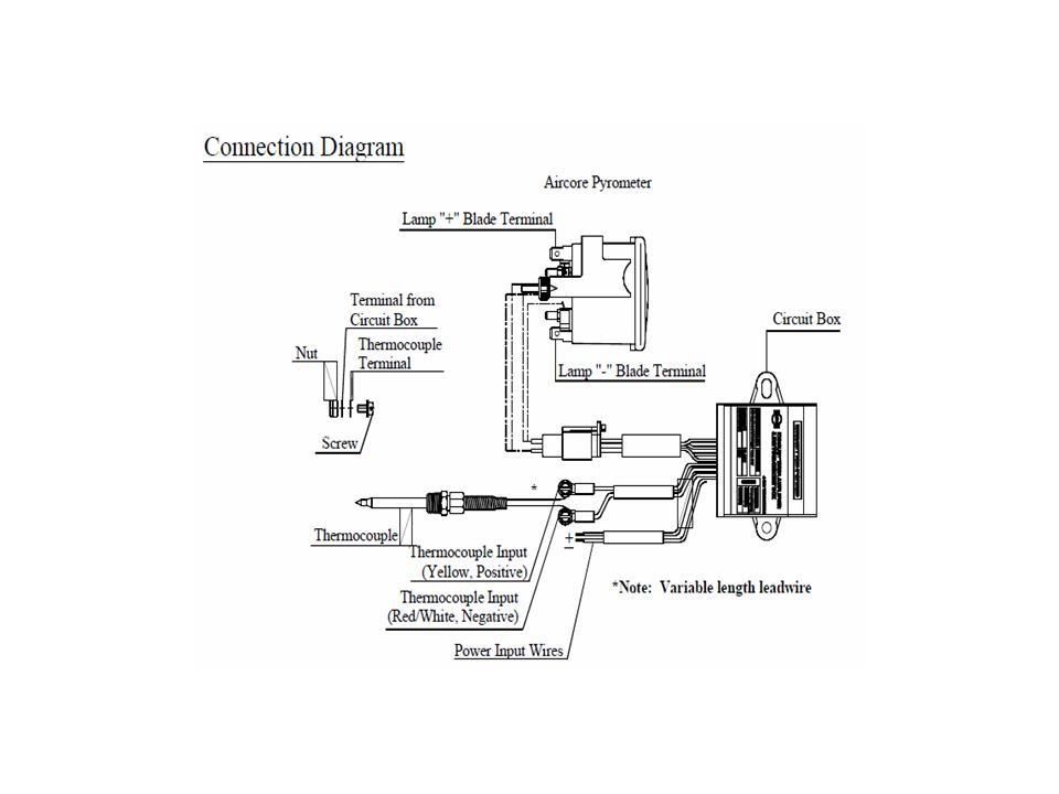
Using a 1/8" NPT tap, tap the hole. Apply a small amount of anti-seize lubricant to the threads of the fitting and tighten. Insert the probe with its nut and ferrule. You want the tip of the probe to be in the center of the exhaust flow. Usually this means that it will need to be inserted 1 inch past the threads that you tapped. Tighten the nut no more than 1 full turn past finger tight. Connect the thermocouple wires to the lead wire using the supplied nuts and heat protective sleeves. You will be connecting the thermocouple to the end of the lead wire that has a long red lead and a shorter yellow lead.

2) Thermocouple Connection:
Connect the red/white color (negative -) wire to the red thermocouple/leadwire.
Connect the yellow color (positive +) wire to the yellow thermocouple/leadwire.
For easy and effective wire connections, the above wires are provided with a set of screws and nuts.
Leadwire is available in lengths of 6’, 10’, 14’, etc.
IMPORTANT INSTALLATION NOTICE FOR LEADWIRE ONLY
In order to connect the wires from the signal amplifier box to the top of the leadwire, it will be necessary to:
1. Bend the red wire up so as to make it even with the yellow wire.
2. Disassemble the nuts and screws.
3. Slide the fiberglass sleeves over the red and yellow wires.
4. Connect the leadwire and reassemble and tighten the nuts and screws.
5. Pull the fiberglass sleeves over the connections.
click the pdf link below to see the wiring diagram
link to more pics & info.
http://www.dieselmanor.com/docs/isspro/ISSPRO-IS026.pdf
Gauge Installations at DieselManor- 1999-2003 7.3L Powerstroke
Using a 1/8" NPT tap, tap the hole. Apply a small amount of anti-seize lubricant to the threads of the fitting and tighten. Insert the probe with its nut and ferrule. You want the tip of the probe to be in the center of the exhaust flow. Usually this means that it will need to be inserted 1 inch past the threads that you tapped. Tighten the nut no more than 1 full turn past finger tight. Connect the thermocouple wires to the lead wire using the supplied nuts and heat protective sleeves. You will be connecting the thermocouple to the end of the lead wire that has a long red lead and a shorter yellow lead.
2) Thermocouple Connection:
Connect the red/white color (negative -) wire to the red thermocouple/leadwire.
Connect the yellow color (positive +) wire to the yellow thermocouple/leadwire.
For easy and effective wire connections, the above wires are provided with a set of screws and nuts.
Leadwire is available in lengths of 6’, 10’, 14’, etc.
IMPORTANT INSTALLATION NOTICE FOR LEADWIRE ONLY
In order to connect the wires from the signal amplifier box to the top of the leadwire, it will be necessary to:
1. Bend the red wire up so as to make it even with the yellow wire.
2. Disassemble the nuts and screws.
3. Slide the fiberglass sleeves over the red and yellow wires.
4. Connect the leadwire and reassemble and tighten the nuts and screws.
5. Pull the fiberglass sleeves over the connections.
click the pdf link below to see the wiring diagram
link to more pics & info.
http://www.dieselmanor.com/docs/isspro/ISSPRO-IS026.pdf
Gauge Installations at DieselManor- 1999-2003 7.3L Powerstroke
#6
07-19-2008, 04:18 PM
Post Fiend
#7
07-19-2008, 04:38 PM
Trending Topics
#8
07-19-2008, 08:09 PM

#9
07-19-2008, 08:11 PM
Post Fiend

#10
07-19-2008, 08:43 PM

#12
07-19-2008, 09:49 PM
Post Fiend
Join Date: Sep 2006
Location: Millbrook Alabama
Posts: 5,584
Likes: 0
Received 0 Likes
on
0 Posts
#14
07-20-2008, 12:29 AM
Post Fiend
Join Date: Feb 2006
Location: Middle Tennessee
Posts: 11,892
Likes: 0
Received 0 Likes
on
0 Posts
#15
07-20-2008, 07:45 AM
Just got home and i'll give the run down, had some time Sat morning before the family came over for a swim and eats to at least get the pillar and gauges wired and set up because i knew i wasn't going to get it all done. Everything is done except the for powering them up and the pyro tap. Boost is done also. Here,s where i got fustrated, after getting everything in and set up i look to see where the other end of the pyro ring terminal leads hook into. First thing i thought they went to the junction box, i look, no not there. I said O-S, does it go to the gauge after installing the pillar already. (following all the directions to a tee) After freakin out i turned to you guys for some help and you responded fast. Brandon PM,ed me and told me to call him and i did, while talking to him and running down the problem i pulled the carpet back under the dash and there was the ring leads that came off the box i needed to connect to the pyro wire. Man o man, brain fart, big time. Does it happen, yes but when you got a great bunch of people helping out like this it make,s it all worth while, thanks again. I'll report back in a little bit after i do the tap pre-turbo and powering it up.