
torque specs?
#1
 10-19-2007, 09:40 PM


Join Date: Sep 2007
Posts: 9
Likes: 0
Received 0 Likes
on
0 Posts
torque specs?
Anyone know the torque specs for the tie rods on a 99 f-250 super duty?
I plan on replacing the inner and outer tie rods, on both the left and right sides. They are all REALLY loose.
Any advice on the replacement would be helpfull as well, since its the first time I've replaced tie rods on this truck.
I plan on replacing the inner and outer tie rods, on both the left and right sides. They are all REALLY loose.
Any advice on the replacement would be helpfull as well, since its the first time I've replaced tie rods on this truck.
#2
10-19-2007, 10:48 PM
Post Fiend
Join Date: Feb 2006
Location: Middle Tennessee
Posts: 11,892
Likes: 0
Received 0 Likes
on
0 Posts
I only have data going back to a 2000MY but think it should be the same.
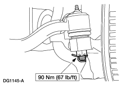
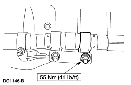
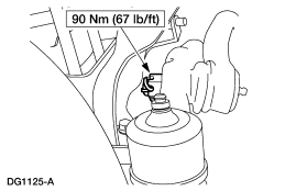
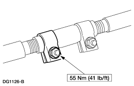
Tie rod ends get 67lbft, the steering adjuster sleeve clamps get 41lbsft. If you remove the tie rods, make sure to count the number of turns and replace the same way. You did not mention whether it was a 4x4 or not. A little more to it with that. Good luck.
Tie rod ends get 67lbft, the steering adjuster sleeve clamps get 41lbsft. If you remove the tie rods, make sure to count the number of turns and replace the same way. You did not mention whether it was a 4x4 or not. A little more to it with that. Good luck.
#3
10-20-2007, 10:37 AM
Join Date: Sep 2007
Posts: 9
Likes: 0
Received 0 Likes
on
0 Posts
#4
10-20-2007, 11:32 AM
Post Fiend
Join Date: Feb 2006
Location: Middle Tennessee
Posts: 11,892
Likes: 0
Received 0 Likes
on
0 Posts
#5
10-20-2007, 12:21 PM

Originally Posted by Tenn01PSD350
I only have data going back to a 2000MY but think it should be the same.
Tie rod ends get 67lbft, the steering adjuster sleeve clamps get 41lbsft.
Tie rod ends get 67lbft, the steering adjuster sleeve clamps get 41lbsft.
-----------------------------------------------------------------------------
<TABLE width="95%"><TBODY><TR><TD>SECTION 211-03: Steering Linkage
</TD><TD align=right>1999 F-Super Duty 250-550 Workshop Manual
</TD></TR><TR><TD>REMOVAL AND INSTALLATION
</TD><TD align=right>Procedure revision date: 01/26/2000</TD></TR></TBODY></TABLE>
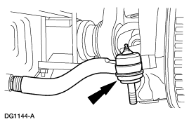
<HR>Tie Rod End�Outer, RH, F-250, F-350, 4x4, and F-450, F-550
<META content="Tie Rod End�Outer, RH, F-250, F-350, 4x4, and F-450, F-550" name=tps_proctitle>
<TABLE cellSpacing=0 cellPadding=3 width="50%" border=1><CAPTION>Special Tool(s)</CAPTION><TBODY><TR vAlign=top><TD>
 </TD><TD vAlign=top>Steering Arm Remover
 211-003 (T64P-3590-F) or Equivalent</TD></TR></TBODY></TABLE>
Removal
NOTE: Replace the tie rod end if the ball stud is loose in the socket or the tie rod end is bent. Replace the front suspension steering ball stud dust seal if any nicks, cuts or tears are present. Do not attempt to straighten a bent toe rod end.
- Position and lock the wheels in the straight-forward position. Raise and support the vehicle; for additional information, refer to Section 100-02.
- Remove the wheel; for additional information, refer to Section 204-04.
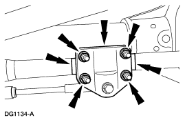
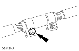
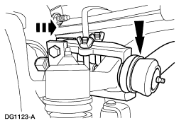
- Loosen the adjusting sleeve clamps.
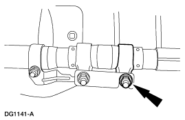
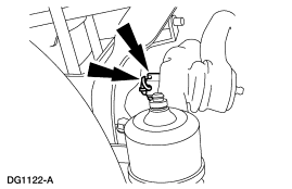
- Mark the steering damper position. Remove the nuts, washers, and two U-bolts. Position the steering damper out of the way.
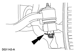
- Remove the cotter pin and castellated nut. Discard the cotter pin.
- Disconnect and position the tie rod end (3A131) out of the way.
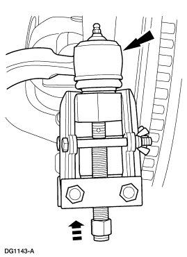
- Use the Steering Arm Remover.
- Remove the cotter pin and castellated nut. Discard the cotter pin.
- Disconnect the tie rod end.
- Use the Steering Arm Remover.
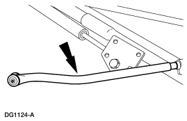
- Remove the tie rod end.
- Note the number of turns required to remove the tie rod end.
- Remove the adjusting sleeve clamp.
Installation
- Follow the removal procedure in reverse order.
- Install a new cotter pin.
- Check the toe-in and clear vision settings; for additional information, refer to Section 204-00.
Stewart
#6
10-20-2007, 12:27 PM
<TABLE width="95%"><TBODY><TR><TD>SECTION 211-03: Steering Linkage
</TD><TD align=right>1999 F-Super Duty 250-550 Workshop Manual
</TD></TR><TR><TD>REMOVAL AND INSTALLATION
</TD><TD align=right>Procedure revision date: 01/26/2000</TD></TR></TBODY></TABLE>
<HR>Tie Rod End�Outer, LH, F-250, F-350, 4x4, and F-450, F-550
<META content="Tie Rod End�Outer, LH, F-250, F-350, 4x4, and F-450, F-550" name=tps_proctitle>
<TABLE cellSpacing=0 cellPadding=3 width="50%" border=1><CAPTION>Special Tool(s)</CAPTION><TBODY><TR vAlign=top><TD></TD><TD vAlign=top>Steering Arm Remover
211-003 (T64P-3590-F) or Equivalent</TD></TR></TBODY></TABLE>
Removal
NOTE: Replace the tie rod end if the ball stud is loose in the socket or the tie rod end is bent. Replace the front suspension steering ball stud dust seal if any nicks, cuts or tears are present. Do not attempt to straighten a bent tie rod end.
Installation
Stewart
</TD><TD align=right>1999 F-Super Duty 250-550 Workshop Manual
</TD></TR><TR><TD>REMOVAL AND INSTALLATION
</TD><TD align=right>Procedure revision date: 01/26/2000</TD></TR></TBODY></TABLE>
<HR>Tie Rod End�Outer, LH, F-250, F-350, 4x4, and F-450, F-550
<META content="Tie Rod End�Outer, LH, F-250, F-350, 4x4, and F-450, F-550" name=tps_proctitle>
<TABLE cellSpacing=0 cellPadding=3 width="50%" border=1><CAPTION>Special Tool(s)</CAPTION><TBODY><TR vAlign=top><TD>
</TD><TD vAlign=top>Steering Arm Remover 211-003 (T64P-3590-F) or Equivalent</TD></TR></TBODY></TABLE>
Removal
NOTE: Replace the tie rod end if the ball stud is loose in the socket or the tie rod end is bent. Replace the front suspension steering ball stud dust seal if any nicks, cuts or tears are present. Do not attempt to straighten a bent tie rod end.
- Position and lock the wheels in the straight-forward position. Raise and support the vehicle; for additional information, refer to Section 100-02.
- Remove the wheel; for additional information, refer to Section 204-04.
- Loosen the adjusting sleeve clamp.
- Remove the cotter pin and castellated nut. Discard the cotter pin.
- Disconnect the tie rod end.
- Use the Steering Arm Remover.
- Remove the tie rod end.
- Note the number of turns required to remove the tie rod end.
Installation
- Follow the removal procedure in reverse order.
- Install a new cotter pin.
- Check the toe-in and clear vision settings; for additional information, refer to Section 204-00.
Stewart
#7
10-20-2007, 12:34 PM
<TABLE width="95%"><TBODY><TR><TD>SECTION 211-03: Steering Linkage
</TD><TD align=right>1999 F-Super Duty 250-550 Workshop Manual
</TD></TR><TR><TD>REMOVAL AND INSTALLATION
</TD><TD align=right>Procedure revision date: 01/26/2000</TD></TR></TBODY></TABLE>
<HR>Tie Rod End�Inner, F-250, F-350, 4x4, and F-450, F-550
<META content="Tie Rod End�Inner, F-250, F-350, 4x4, and F-450, F-550" name=tps_proctitle>
<TABLE cellSpacing=0 cellPadding=3 width="50%" border=1><CAPTION>Special Tool(s)</CAPTION><TBODY><TR vAlign=top><TD></TD><TD vAlign=top>Steering Arm Remover
211-003 (T64P-3590-F) or Equivalent</TD></TR></TBODY></TABLE>
Removal
NOTE: Replace the tie rod end (3A131) if the ball stud is loose in the socket or the tie rod end is bent. Replace the front suspension steering ball stud dust seal if any nicks, cuts or tears or present. Do not attempt to straighten a bent tie rod end.
Installation
Hope those help.
Stewart
</TD><TD align=right>1999 F-Super Duty 250-550 Workshop Manual
</TD></TR><TR><TD>REMOVAL AND INSTALLATION
</TD><TD align=right>Procedure revision date: 01/26/2000</TD></TR></TBODY></TABLE>
<HR>Tie Rod End�Inner, F-250, F-350, 4x4, and F-450, F-550
<META content="Tie Rod End�Inner, F-250, F-350, 4x4, and F-450, F-550" name=tps_proctitle>
<TABLE cellSpacing=0 cellPadding=3 width="50%" border=1><CAPTION>Special Tool(s)</CAPTION><TBODY><TR vAlign=top><TD>
</TD><TD vAlign=top>Steering Arm Remover 211-003 (T64P-3590-F) or Equivalent</TD></TR></TBODY></TABLE>
Removal
NOTE: Replace the tie rod end (3A131) if the ball stud is loose in the socket or the tie rod end is bent. Replace the front suspension steering ball stud dust seal if any nicks, cuts or tears or present. Do not attempt to straighten a bent tie rod end.
- Position and lock the wheels in the straight-forward position. Raise and support the vehicle; for additional information, refer to Section 100-02.
- Remove the RH wheel; for additional information, refer to Section 204-04.
- Loosen the adjusting sleeve clamp.
- Remove the cotter pin and castellated nut. Discard the cotter pin.
- Disconnect the tie rod end.
- Use the Steering Arm Remover.
- Remove the tie rod end.
- Note the number of turns required to remove the tie rod end.
Installation
- Follow the removal procedure in reverse order.
- Install a new cotter pin.
- Check the toe-in and clear vision settings; for additional information, refer to Section 204-00.
Hope those help.
Stewart
Trending Topics
#8
10-21-2007, 04:20 PM
Join Date: Sep 2007
Posts: 9
Likes: 0
Received 0 Likes
on
0 Posts

Thread
Thread Starter
Forum
Replies
Last Post
MONAVIERONJON
1999 to 2016 Super Duty
4
08-18-2014 12:37 PM