
Hooking up high idle w/upfitter switches

#92
 11-07-2012, 07:27 PM
Senior User
Join Date: Sep 2012
Location: DFW, TX
Posts: 168
Likes: 0
Received 0 Likes
on
0 Posts
BP Thank you! That's exactly what I wanted to know, and with that explanation I have a perfect visual of what's going on now! If something like that generator, or air compressor or whatever needed 1200 rpms to run it, the tranny would be spinning at 1200 to power that because the TC would lock up and match the engine rpms! GOT IT! Makes perfect sense. I'll catch up eventually. LOL
That being said, I wonder if the people that have the other way slowly creep up may have failing alternator or batteries starting to not hold charge? Just a thought.
Thanks again
That being said, I wonder if the people that have the other way slowly creep up may have failing alternator or batteries starting to not hold charge? Just a thought.
Thanks again
#93
02-03-2013, 04:17 PM

#94
04-29-2013, 05:36 AM

#95
03-13-2014, 01:25 PM

I realize this is an old topic, but I experienced similar difficulties with my 2011 F250 6.2l SEIC mod.
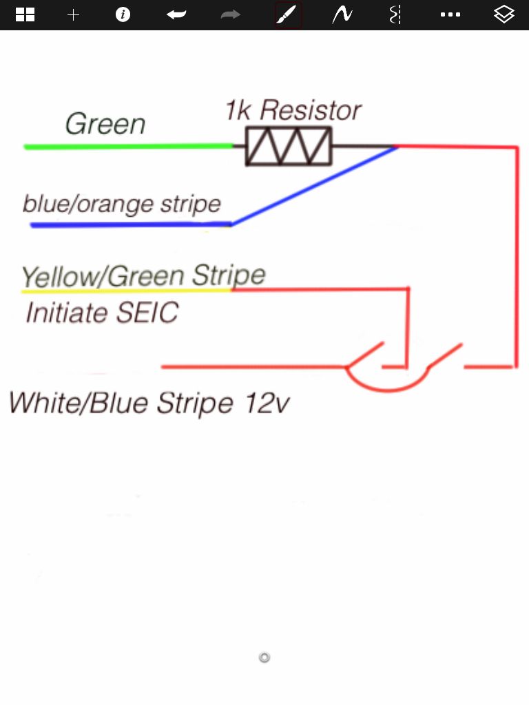
What I found was that I needed 2 switches. One provides 12v+ to the Yellow/green stripe (PTO_Request), which enables standby mode 900rpm. The second switch provides 12v+ to the PTO_Engage (Blue/orange stripe) and the PTO_rpm (Green). Place the desired resistor between the green wire and 12v.
Flip the standby mode switch, then the rpm switch... Voila.
#96
09-20-2014, 12:44 PM
Senior User
Join Date: Jul 2014
Location: Riverton, Wyo
Posts: 164
Likes: 0
Received 0 Likes
on
0 Posts
#97
10-10-2014, 12:33 PM

finally got it
Thanks rjcorazza! That got mine working. If you read the instructions in the SEIC mod, it does say to "apply power to SEIC enable, and then apply power to...". I guess you have to take it literally. Thanks for your help, I probably would not have figured that out on my own!
#98
10-10-2014, 07:56 PM
Glad it worked out. I can't take credit for the solution though... I read about using a relay that somehow powers both wires separately, and a preliminary test was to use 2 switches first before wiring in the relay. I just quit at 2 switches which gives me 900 rpm with the first and my selected rpm with the second. Previous solution was a cut off carbon arrow shaft with adjustable rpm threaded field tip.
#99
06-11-2016, 06:26 PM
Freshman User
Join Date: Mar 2005
Location: California
Posts: 34
Likes: 0
Received 0 Likes
on
0 Posts
Doesn't seem to work on my truck
I need some help, please, I don't know what either I'm doing wrong, or what is wrong with my truck but I can't get this mod to work on my truck.
Truck- 2005 F250 V10
I have the factory upfitter switches installed.
1- I connected a wire from the acc #4 (orange w/ light blue stripe) to the solid orange wire in the SEIC bundle. started the truck, flipped the switch and no rpm change.
I confirmed that:
- truck was in park
- truck was running/ idling
- parking brake on
- all my brake lights work
- tried with driver door open, and tried with it closed
the RPM did not increase. even tried flipping the other switches just in case, and no rpm change.
2- I disconnected the wire and got my volt meter out. Confirmed upfitter switch works.
3- I tried a jumper wire to the green/ red wire (my truck doesn't have a green and purple wire) and this was the closest to it. still didn't work.
My truck does have a label on the wires with the following breakdown:
LG-W CTO
W-O VSOUT
R-W NEUTRAL
LG-R PARK
O PTO-MODE
O-W PTO-ENGAGE
O-LB PTO INDICATOR
O-Y PTO-RPM SELECT
Am I missing something obvious? Should I be using one of these other wires instead? Any help is appreciated.
Thanks
#100
06-11-2016, 07:27 PM
Tuske, look at my post #55. Download that document.
It sounds like you were trying to use the BCP function. But that is diesel only. It is more complicated for gas engines, and I have not done one personally, but I think you will need 2 switches, which have to be engaged sequentially. Does not look like just flipping 1 switch will do it. A resistor or potentiometer will be needed. Check that document carefully, and be sure you are using the correct section for your gas F-series. Even the gas E-series is a separate section.
It sounds like you were trying to use the BCP function. But that is diesel only. It is more complicated for gas engines, and I have not done one personally, but I think you will need 2 switches, which have to be engaged sequentially. Does not look like just flipping 1 switch will do it. A resistor or potentiometer will be needed. Check that document carefully, and be sure you are using the correct section for your gas F-series. Even the gas E-series is a separate section.
#101
06-11-2016, 11:20 PM
Freshman User
Join Date: Mar 2005
Location: California
Posts: 34
Likes: 0
Received 0 Likes
on
0 Posts
Tuske, look at my post #55. Download that document.
It sounds like you were trying to use the BCP function. But that is diesel only. It is more complicated for gas engines, and I have not done one personally, but I think you will need 2 switches, which have to be engaged sequentially. Does not look like just flipping 1 switch will do it. A resistor or potentiometer will be needed. Check that document carefully, and be sure you are using the correct section for your gas F-series. Even the gas E-series is a separate section.
It sounds like you were trying to use the BCP function. But that is diesel only. It is more complicated for gas engines, and I have not done one personally, but I think you will need 2 switches, which have to be engaged sequentially. Does not look like just flipping 1 switch will do it. A resistor or potentiometer will be needed. Check that document carefully, and be sure you are using the correct section for your gas F-series. Even the gas E-series is a separate section.
-Brendon
#102
06-12-2016, 12:32 PM
Freshman User
Join Date: Jul 2008
Location: El Cajon, CA
Posts: 40
Likes: 0
Received 0 Likes
on
0 Posts
This is a step by step DIY that I posted over on DB.
Little DIY High Idle for you guys - Diesel Bombers
Little DIY High Idle for you guys - Diesel Bombers
#103
09-28-2016, 09:37 PM


#104
01-26-2019, 03:30 PM
FTE Chapter Leader
Probably should use this one for your 2005. It's probably essentially the same, but you never know.
https://www.fleet.ford.com/truckbbas/non-html/Q108.pdf
https://www.fleet.ford.com/truckbbas/non-html/Q108.pdf
Thanks
#105
01-26-2019, 07:11 PM
@bpounds Looks like a lot of the links have died. Did you happen to save any of the PDFs locally?
Thanks
Thanks
I moved it to my G-drive. Click this link to download. https://drive.google.com/file/d/1JA_...ew?usp=sharing
For other years, I would suggest anyone interested try one of the internet history sites, or just a Google search for using the original document name. I'm sure these are all lurking out there in a bunch of places.