Where's the Ammeter Shunt?
#1
 08-31-2005, 01:27 AM

Where's the Ammeter Shunt?
I recently bought a 1986 F250 Super Cab 4x4 with carbureted 460, 4 speed, 3.55 axles and 8,800 GVWR. (Yeah, I know, a nice economy car for the times.") ) I see the truck has factory gauges, including an ammeter. I would expect a factory ammeter to be the shunt type.
) I see the truck has factory gauges, including an ammeter. I would expect a factory ammeter to be the shunt type.
I want to add headlight relays and maybe a few other electrical loads. If I want the ammeter to tell the truth, I need to make sure all loads are on the same side of the ammeter as the alternator, with the battery on the other side.
Where should I look for the ammeter shunt on this truck (and what does it look like)?
Thanks,
Lane
) I see the truck has factory gauges, including an ammeter. I would expect a factory ammeter to be the shunt type. I want to add headlight relays and maybe a few other electrical loads. If I want the ammeter to tell the truth, I need to make sure all loads are on the same side of the ammeter as the alternator, with the battery on the other side.
Where should I look for the ammeter shunt on this truck (and what does it look like)?
Thanks,
Lane
#3
08-31-2005, 04:16 AM
 Now I'll know what to look for.
#4
12-27-2012, 05:26 PM
I know this is an old thread. Very old. I've seen this question before in threads primarily dealing with 3G alternator conversions. Usually th answer is to just forget about the ammeter and put a voltmeter under the dash or something. Yet it should be possible once you locate the shunt, to replace it with another of the correct value so the ammeter works correctly and safely. So the question remains. Where, physically on the truck, is the shunt? We need only know the current which send the ammeter to it's limit and the max limit of our alternator (I think it's suggested that you use a 175A fuse) and we can work out the correct value of the shunt to use.
#5
12-27-2012, 05:54 PM

There is a thread on here in the past few days that has talked about this shunt. I think it was Gary who figured the shunt resistance was about .002 ohms. I am wondering how you are going to "buy this" thing. We were talking about balling up 9 1/2 inches of 14 gauge wire, and that would be close to the correct value, and trim it from there for the gauge to read correctly.
How do you feel about your new high output 3g 130 amp alternator having to go through 9 1/2 feet of 14 gauge wire?
Do you think the factory ammeter can handle a 130 amp reading?
I will repeat what you said you found in most other posts(I was probably the one saying it). Using the factory ammeter with a 3g upgrade is just a bad idea. Use a voltmeter like the factory did when they used the 3g.
#6
12-27-2012, 08:28 PM
I have no plan to send any more current than the ammeter was originally designed to handle, which I believe was found to be about five amperes. The vast majority of the current travels down the heavy cable between the alternator and the battery positive terminal. That in effect is your primary shunt. So the ammeter is in parallel with this, but there must still be yet another shunt as mentioned. Though the ammeter never sees but a small percentage of the current flowing between the battery and the alternator, if calibrated correctly it will read a charge or discharge state proportional to what is actually going on in the charging system. I could find the appropriate values either by calculation or experimentally, using a multimeter and a 5A fuse to protect the wiring in the harness, and also fiddle with the gauge by itself connected to a voltage divider circuit on a breadboard to find how much current makes it go to it's limit. But ultimately I will need to find that original shunt...
#7
12-27-2012, 08:53 PM

Post Fiend
Join Date: Jul 2004
Location: Northern California
Posts: 8,786
Likes: 0
Received 18 Likes
on
17 Posts
The Ammeter Shunt is in the Alternator wiring.
Between the Fuse Link coming off the starter solenoid, and the ammeter wires respectfully.
Would be wiser to buy a commercially avaliable ammeter shunt than to hard wire something haphazardly. Do a search for ammeter shunts. There is a wide variety of values avaliable.
Between the Fuse Link coming off the starter solenoid, and the ammeter wires respectfully.
Would be wiser to buy a commercially avaliable ammeter shunt than to hard wire something haphazardly. Do a search for ammeter shunts. There is a wide variety of values avaliable.
Trending Topics
#8
12-27-2012, 09:29 PM
The AMP gauge has a full scale reading with about 1 amp.
here is a good read...
https://www.ford-trucks.com/forums/1...th-photos.html
I gave up, my amp meter is just a non working.
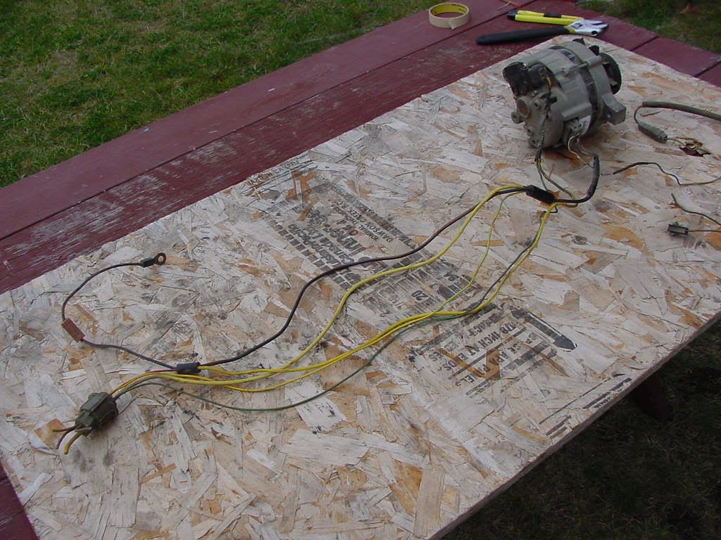
Here is a photo with the shunt wire (black wire) between the 2 black splices.
Jim
.
here is a good read...
https://www.ford-trucks.com/forums/1...th-photos.html
I gave up, my amp meter is just a non working.
Here is a photo with the shunt wire (black wire) between the 2 black splices.
Jim
.
#9
12-27-2012, 10:42 PM
Thank you very much for your advice, definitely food for thought. There must be something we're missing here though. If it's proven that full scale of the ammeter is + or - one amp, then it can't be anything more than changing the value of the shunt. The change must be very small though, as one amp is a tiny fraction of the overall current that could hypothetically be flowing in a charging system with a 130A-150A alternator. Another possibility, in the name of preserving the integrity of the stock cluster, i to come up with a circuit that looks at the voltage in the charging system and flip-flops a current through the ammeter based on a reference voltage of say, 13.7-14.2V. That's more advanced than anything I could come up with off hand, but I bet it's possible.
#10
12-28-2012, 01:10 AM

i would think it possible to place an OEM-style voltmeter in the factory cluster and get a simple and effective system that way.
or you can simply add an idiot light like i did here https://www.ford-trucks.com/forums/1...with-pics.html my rig has 2 alternators powering seperate systems, with 2 idiot light right above the ammeter. most of us just need one. as i describe there, its a real simple thing to add in, it doesn't take the space of another gage, and its as good as any other idiot light which is commonly found on cars with a 3g alternator
or you can simply add an idiot light like i did here https://www.ford-trucks.com/forums/1...with-pics.html my rig has 2 alternators powering seperate systems, with 2 idiot light right above the ammeter. most of us just need one. as i describe there, its a real simple thing to add in, it doesn't take the space of another gage, and its as good as any other idiot light which is commonly found on cars with a 3g alternator
#11
12-28-2012, 02:22 PM
Post Fiend
Join Date: Jul 2004
Location: Northern California
Posts: 8,786
Likes: 0
Received 18 Likes
on
17 Posts
Thank you very much for your advice, definitely food for thought. There must be something we're missing here though. If it's proven that full scale of the ammeter is + or - one amp, then it can't be anything more than changing the value of the shunt. The change must be very small though, as one amp is a tiny fraction of the overall current that could hypothetically be flowing in a charging system with a 130A-150A alternator. Another possibility, in the name of preserving the integrity of the stock cluster, i to come up with a circuit that looks at the voltage in the charging system and flip-flops a current through the ammeter based on a reference voltage of say, 13.7-14.2V. That's more advanced than anything I could come up with off hand, but I bet it's possible.
The voltage doesn't change between the shunt and the ammeter wiring. 12v average. It's the amperage to the ammeter that changes.
12v at plus or minus .5 to 1 amp will not affect the ammeter adversely.
12v at plus or minus 130 amps will fry it like an egg and cause a fire.
The shunt alows 99% of the amperage to bypass the ammeter. The voltage remains the same between the two however...
Think of the circut loosely (as it's not really the same, but the ideas are relative) like a lightbulb in your house. 120v/60 watt incandecent bulb will use more electricity than a 120v/14w flourecent. the voltage remains constant, it's the watts that change. Similar (but not equal) to the ammeter circut and the shunt. The voltage remains the same, but the amperage is divided with the majority going through the shunt, and aproximately 1% of the amperage going to the ammeter.
More info here...
Ammeter design : Dc Metering Circuits
#12
12-28-2012, 05:17 PM
We had a debate about this before in another thread. I called the factory ammeter a "very sensitive voltmeter". Some people did not like that, and put forth the fact that is was still a ammeter, but the shunt just split the current between the ammeter and the shunt itself, the shunt taking the majority of the current.
Both ways of looking at it are correct. The fact is, you can't have current without voltage being there, and you can't have voltage without current being there. If you look at the link in the above post, in their example, they have .001 amps going through their ammeter, and they also have .5v across the ammeter. So you can look at it both ways, the shunt is splitting out .001 amp to the ammeter, or the ammeter is reading .5v full scale across the shunt. You would be correct in either case.
It's something you need to think about in the factory setup. You will lose a little bit through the shunt, as it does create a very small voltage drop across it. If you design for it, then fine. It can be considered formula wise just like a resistor, so it will need to dissipate a certain amount of heat. If you put a shunt in the system with a 130 amp alternator, the shunt would have to be much larger, it's size would have to be calculated as well as it's resistance to give full scale to the factory ammeter.
#13
12-28-2012, 06:04 PM
Posting Legend
I'm a little late to this thread, but a few days ago I ran a test on four different ammeters from gauge clusters that I have for these trucks, and found that it takes from .102 volts (@ .6 amp) to .156 volts (@ .94 amp) to show full scale.
And, here's a link to the thread where this was discussed, as Dave mentioned: Gauge voltage regulator. And, in that thread you'll find the discussion of making your own shunt. I made the statement there that I'd be happy to calculate the shunt value you'll need for any given current in order to make the ammeter go to full scale.
Further, I agree wholeheartedly with what Dave said about it being a very sensitive voltmeter or an ammeter. He is absolutely spot-on. You take one side of the argument and I'll take the other - your pick.
#14
12-29-2012, 01:07 AM
I don't think I could ever conceive of these things as volt meters. The voltage observed (.102-.156) could be seen as a constant between two potential sources of power that will always yield .6 or .94 amperes through the meter. One thing that bothers me in the discussion about which shunt value to use is that the resistance values must be fairly precise (.XXX Ohms) for the gauge to be effective. However if you consider how easy it is for the resistance to change in the average harness, the gauge could be rendered useless fairly easily. This is mostly because of the very small 'sampling' of current the gauge sees, with probably 99.9% traveling through the big cable between the alternator and battery. In the aftermarket gauges for 40-60A systems it's more feasible to shunt 100% of the charge current through the ammeter, which would provide a pretty reliable indicator. But in a 100A system it's not such a bright idea. It surely must be possible to build a circuit that looks at the voltage at an input and varies a current in both polarity and level in the output. Kind of like a reverse op-amp kind of thing...
#15
12-29-2012, 02:12 AM

I called the factory ammeter a "very sensitive voltmeter".
I agree with your notion that the voltage dropped across the shunt wire could be measured by a very sensitive voltmeter.
A volt meter draws almost no current as it has a high resistance between the leads. The worse case current through the shunt wire would produce a voltage drop that would not be altered with the meter attached to it. You could verify that with another volt meter measuring the voltage across the shunt with and without the ford amp-meter.
A real current meter however would alter the voltage across the shunt wire as it has a very low resistance between its leads.
Most people when they think of an automotive voltage gauge think of measuring 12V or the charging voltage but you could measure the voltage across a tiny resistor (the shunt wire). To "think" current with your voltage meter you would just need to know the resistance of the shunt wire and do the math: voltage across the shunt divided by the resistance of the shunt and so mark the scale your "ford amp meter".