When you click on links to various merchants on this site and make a purchase, this can result in this site earning a commission. Affiliate programs and affiliations include, but are not limited to, the eBay Partner Network.
My goal here is to share how a '77 F250 is wired and collectively leave information that another person can use to troubleshoot. I caveat my post that some details may not be 100% accurate and that the collective experience of our forum will correct my mistakes (thanks all).
1) The rear brake light fails to operate. Here is a photo of the brake light wiring. To make a light bulb illuminate, you need a good ground and 12 volt of direct current (VDC). While the wiring looks chaotic, you can see two sockets (the top makes the brake light work). Each socket has a wire going to a local ground. One wire is spliced to the rear passenger running lamp (the yellow connector) before it joins the remaining wire to run across to the driver's side rear corner.
2) Here is a photo of the actual bulb socket, complete with carbon buildup on the contact points. The ground wire is connected to the left contact on the socket wall. The running lamp circuit is the left bottom contact. The brake circuit is the right bottom contact.
3) All these wires collect at the driver's side rear into a four prong plug. I'll introduce some measurements and my opinion, as things aren't working as they should. Let's label this connector F1 (upper right hand side), M1, (upper left hand side), M2 (lower left hand side) and M3 (lower right hand side).
Readings with key off and lights off (I'm leaving out any reading less than 1 ohm or VDC):
M2 = 2.4 ohms
M3 = 1.6 ohms
No connections read any voltage
Reading with running lamps on:
M2 = 2 VDC
M3 = 12 VDC
No connections read any resistance
Reading with brake pedal depressed:
F1 = 12 VDC
M2 = 4.2 ohms
M3 = 3.4 ohms
I speculate that I should have another connector with 12 VDC (one for each side lamp to operate).
4) Up to the engine compartment to the next connection point. Doing this will show whether the problem is between the two connections, if readings are different, or further toward the brake pedal, if readings are consistent. Let's label this connection F1 (upper left hand), F2 (upper right hand), M1 (lower left hand) and M2 (lower right hand)
Readings with key off and lights off (I'm leaving out any reading less than 1 ohm or VDC):
F2 = 2ohms
M2 = 2.7 ohms
No connections read any voltage
Reading with running lamps on:
F1 = 12 VDC
M2 = 2.1 VDC
No connections read any resistance
Reading with brake pedal depressed:
F1 = 1.8 ohms
F2 = 12 VDC
M2 = 2.6 ohms
Based on this information, I speculate that I'm still missing a second 12VDC closer toward the brake pedal(?) and that the wiring from the engine compartment to the light socket is okay (maybe not perfect).
5) At this point, I think I need to crawl under the dash and try to find the brake switch, but I'll wait for you to let me know if my assumptions are incorrect.
The side lights and tail lights are powered on one wire in that connector. Turn signal and brake lights share a wire for each tail light for a total of 2 wires Reverse lights are the fourth. The ground is from the socket to the bed and then the bed is grounded through the frame. If the lights are not working like mine were. Check for corrosion in the light sockets and clean or replace as necessary. Then go open the hood and find a 8 pin connector directly outside the drivers side firewall that only uses 7 wires in it. This is were your rear chassis harness begins. My connector looked good but whatever was left of 40 year dielectric dirt was stealing voltage. A ohms meter showed this. Remove the piece of plastic in the middle of the puns and remove one by one to clean them. Reassemble and check to see if your problem is fixed. If no brake lights check brake light switch. No turn signals check flasher, both hazard and turn signal flasher behind dash then to the switch if doesn't fix it. If no tail lights go to the headlight switch. Lastly clean the grounds to bed and make sure to have a good ground from battery to starter, battery to body, and engine to frame. This is the most cause of electrical problems on these trucks is bad grounds.
Thanks both and I should have included the information that my left side brake light works fine and so do the running lights. I read 79's response that a single wire shares the turn signal and brake (makes sense). IF I understand correctly, then may I conclude that two wires and not one should read 12VDC at both connectors that I tested? I definitely am not getting 12VDC at the socket; I've cleaned the local ground spot on the body (dremmel tool to ensure good metal contact) and I've tested the ground from the socket to a remote spot on the frame (i.e. not to where it screws in).
Day two troubleshooting... Since I knew the connector in the engine compartment was only getting one shot of 12VDC (to fire the left tail light), I started from the brake level switch. I kind of followed 79's advice and my wiring diagram and performed a continuity test to a nine-wire connector under the dash.
This nine-wire connector plugs into the steering column. Here is the column side; see any problems here, sports fans? Note to all: unplug the connector - don't cut the wires like the effing moron who preceded me.
Here's my preference when correcting redneck engineering butt splices. I use non-insulated connectors, and test each for continuity.
I then add heat shrink to each connection (slip it over the wire before you crimp the connector!). Here is the final product, and I added some electrical tape to keep the bundle manageable.
Upon replacing all of these "are you kidding me" connections with some that will work through any apocalypse, the right rear brake light starting working again. Was it one of these wires, bumping the nine-pin connector or something else? I cannot say but hopefully this post will help someone in the future.
Last edited by Idaho Highboy; 01-29-2017 at 05:56 PM.
Reason: correct grammer
I'm guessing those wires were cut because the turn signal switch was replaced at one time and the person working on it didn't understand how to re-pin the new switch wires into the OE plug.
Can anyone clarify whether the steering column diameter is different between '73 and '79? What about the column's nine-pin connector; is it different throughout this generation of truck?
Reading redmt79's comment and connecting it to my other mystery: a post titled '77 F250 Steering Column Moves.
The current column's turn signal switch isn't new and I wonder if I have an older / replacement column in my truck. I received a part to tighten things up, but it seems like it's the same one I have in there.
Sorry to muddle two different topics, but this is the joy of purchasing something with 40 years of who-knows-whatery...
Last edited by Idaho Highboy; 01-31-2017 at 02:09 PM.
Reason: update question
Idaho.....I don't know about the difference between '73 and '79........What I do know is that the column in my '78.......came out of a '79 Bronco.......since '78 and '79 were the only years they offered a tilt column.....I really don't know why mine moves......
Can anyone clarify whether the steering column diameter is different between '73 and '79? What about the column's nine-pin connector; is it different throughout this generation of truck?
Reading redmt79's comment and connecting it to my other mystery: a post titled '77 F250 Steering Column Moves.
The current column's turn signal switch isn't new and I wonder if I have an older / replacement column in my truck. I received a part to tighten things up, but it seems like it's the same one I have in there.
Sorry to muddle two different topics, but this is the joy of purchasing something with 40 years of who-knows-whatery...
I happen to have a 73 and a 79 column at home so I can check for differences if I remember when I get there. I don't think there's a diameter difference though, but not 100% positive.
To clarify my earlier comment, new turn signal switches typically do not come with the horseshoe connector attached. This is because you have to fish the wires down the inside of the column. Then standard practice is to un-pin the connector off the old switch harness, and insert pins from the new harness into the connector using the same positions. Or it could be that someone simply decided to cut the harness for a swap, but that seems a bit lackey to me. But you never know with the history of these trucks though!
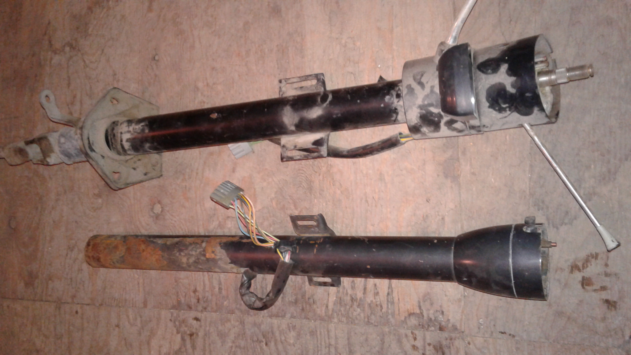
Okay, here's the results of my comparison of a '73 column and '79 column. As I suspected, both are 2-1/4" OD.
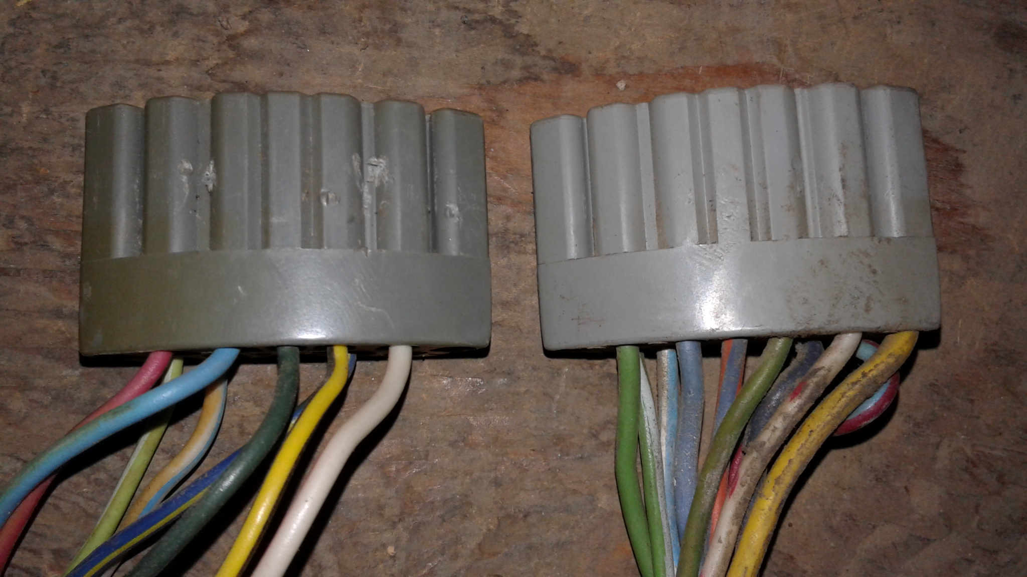
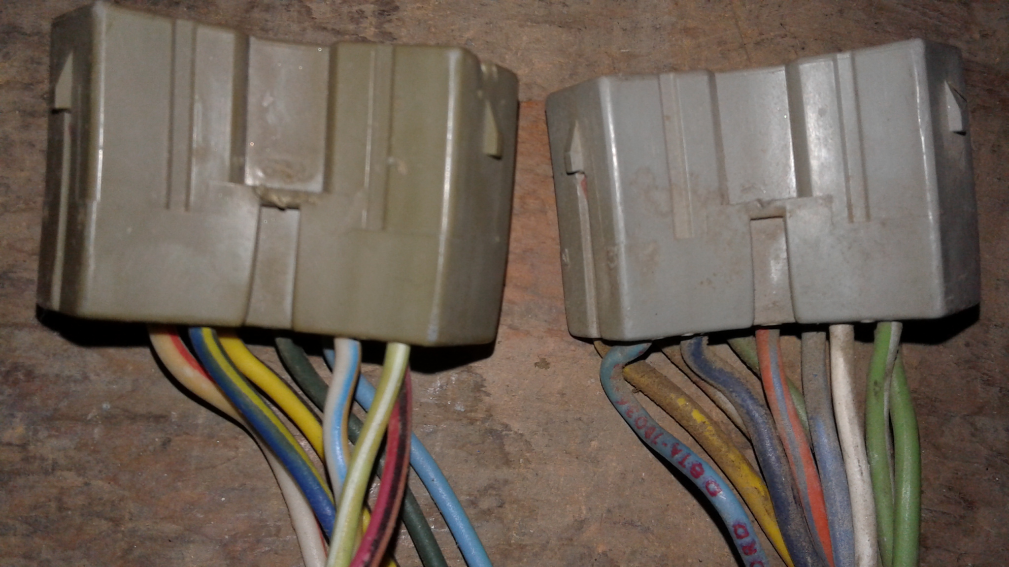
The horseshoe connectors are the same, but wired differently. One would need to compare wiring diagrams to determine the exact differences. As I recall, the later columns were pre-wired for cruise control regardless if the truck was equipped or not. And the later columns also used a two-wire horn circuit. These are a couple potential differences to explain the wiring changes. Also note that this '79 column is an automatic so will have a wire for the backlight on the PRND21 indicator.
You can see the firewall attachment plate on the '79 column - it is a rigid metal piece with grommet around the column tube and rubber gasket on the firewall side of the plate. Based on the info NumberDummy posted in the other thread, it appears the earlier columns used the exterior firewall bracket and clamp arrangement.
Thanks redmt79 ! This is the kind of information I was hoping for, and I also appreciate those that answered ahead of you. Maybe that steering column bushing piece is worn out and the new one will tighten things up.
This evening the right brake light stopped working again. Previously undisclosed is that my turn signal fuse blows about every second day (if I put a fuse in). Sigh...
My next step is to measure continuity (pedal up) and voltage (pedal depressed) from the brake pedal to the nine-pin connector. I suspect that the problem is in between these two points, after this weekend's troubleshooting. I'll review the wiring diagram, as I suspect the wires flow through the signal switch - my primary suspect right now (given both symptoms). If it is the signal switch, I saw another thread detailing how to replace it. The mechanism that returns the switch to the middle is busted anyway. I just don't understand why a circuit can work for an entire day before quitting (and not coming back); really thought I had this fixed...

 01-28-2017, 01:27 PM