When you click on links to various merchants on this site and make a purchase, this can result in this site earning a commission. Affiliate programs and affiliations include, but are not limited to, the eBay Partner Network.
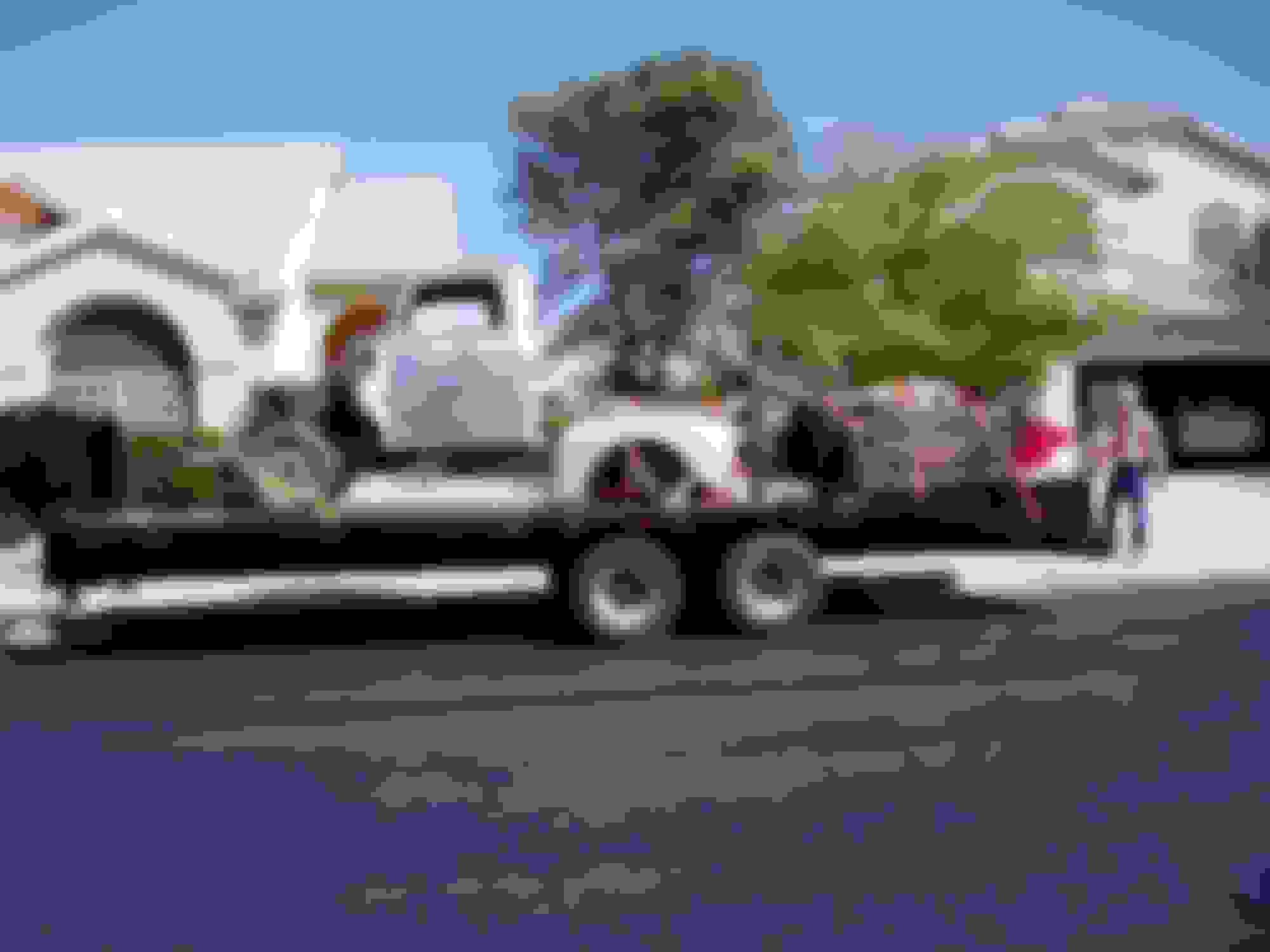
Well I've been hanging out here since 2006, so I guess its past time I started my build thread. I have a 1948 F1 I bought from an ex-body shop owner who was tired of the project and wanted to clean out his garage. I found it posted on the So-Cal Arizona for sale bulletin board. I bought it and hauled it home withe help of my brother-in-law with his diesel truck and heavy equipment trailer. I guess some brothers-in-law are nice guys when they share your love of trucks.
I'm quite a ways into the complete tear down and total rebuild of making this truck a hot rod so it will take a little bit to catch you up on the progress. I'll post pictures and add a link to this thread to the members build thread to help keep track of things. Things like changing jobs, retirement, house remodeling and family stuff slow me down; but I'm making "good" progress along the way, with help from experienced craftsmen and this forum. I do as much as I can myself; but I know my limits so I have farmed out the really important stuff to a good shop I use.
To give you some details, Ford 427 Windsor crate motor, 4R70W automatic transmission, independent front suspension, parallel leaf rear suspension, Ford 9 inch rear end, stock body sheetmetal. To keep track of everything I have a 25 page spreadsheet of all of the parts and cost. I have to keep updating the spreadsheet so it continues to grow.
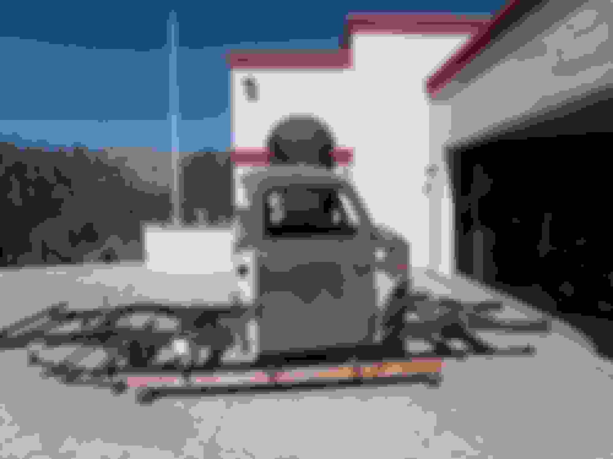
Enough talk for now, so here are some pictures. Truck on my brother-in-laws trailer.
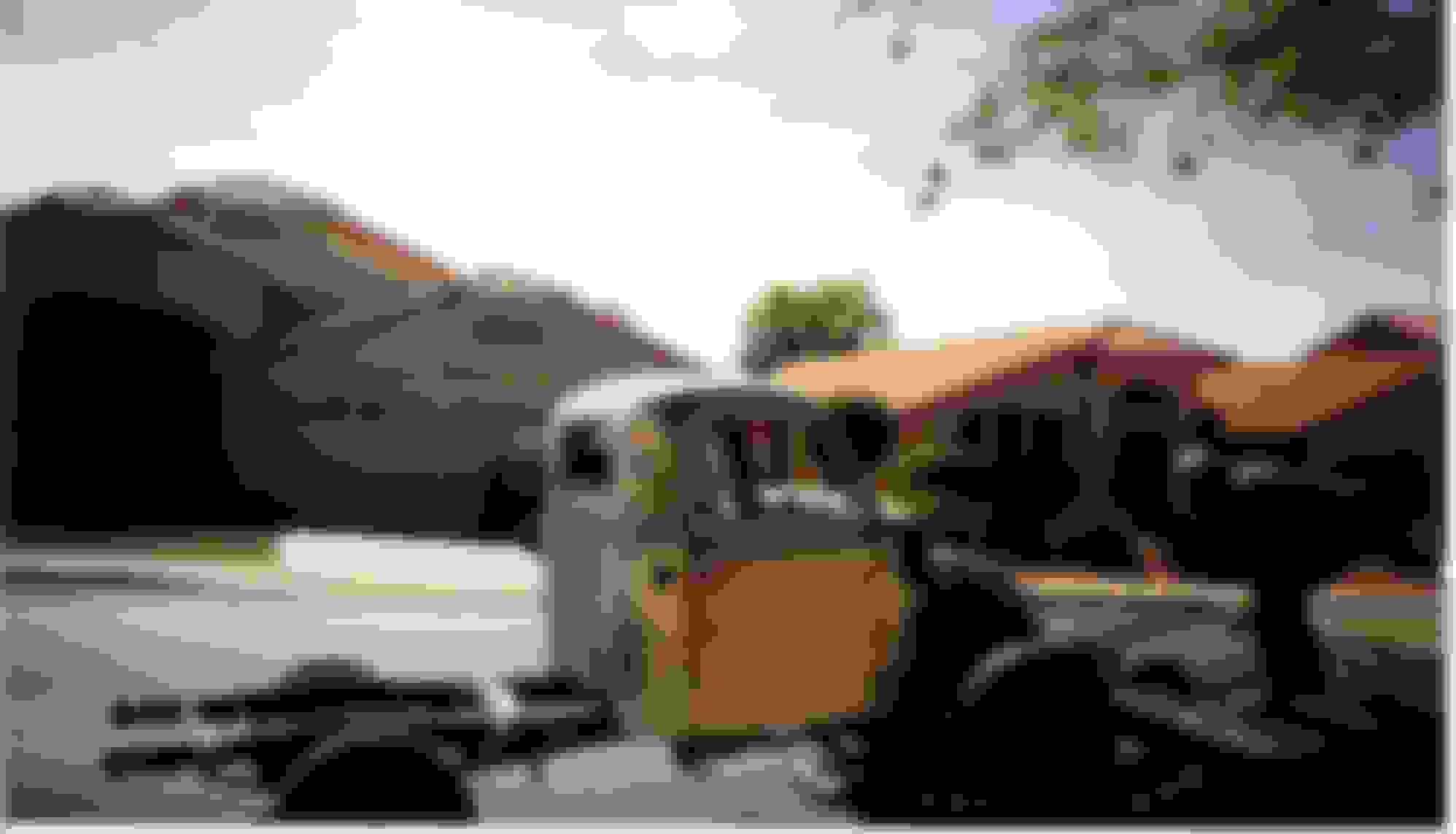
Off load of the truck.
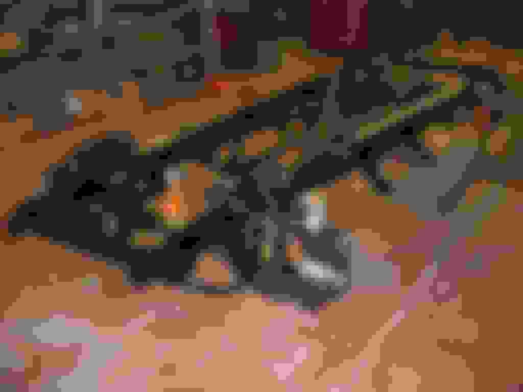
Ford 302 smog motor with C4 automatic.
So thanks for listening and I hope to be of some help to you all. I have already used some information from here so it is time to give back.
Nice starting spot, currently I'm just down the road from ya (staying in the Hampton by the international here is Tucson. Keep the build pictures coming! Have an awesome one
Those first three photos were from 2006. I've been at this a while and since we sold the RV, I have cash with which to do lots of work on this project. I will bring you all up to speed on the build. In 2009 I took a job with the University of Arizona so we moved to Tucson and this is where I now work on my truck, especially since now I am retired.
The previous owner (PO) may have been a former body man, but his design skills on suspensions was abysmal. You'll see the results of that in these next photos.
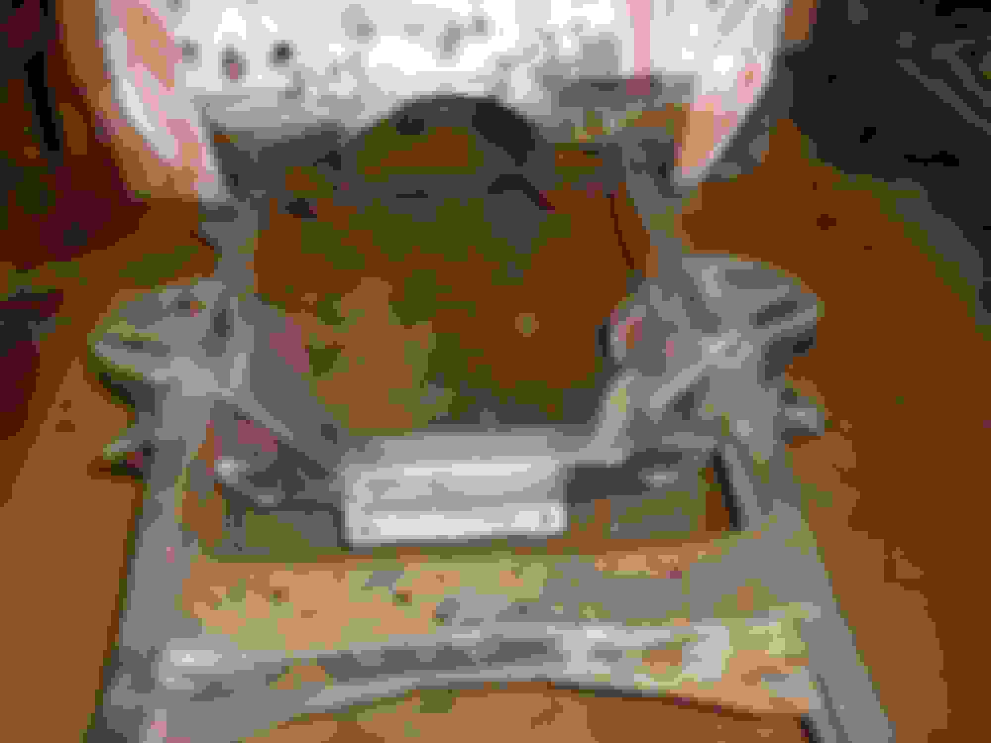
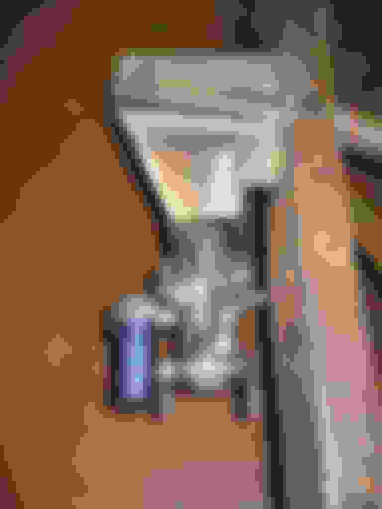
The PO added a big GM power steering box and this was the bracket he built to hold it in place. Note that the front leaf spring has about one inch of travel before it contacts the bracket.
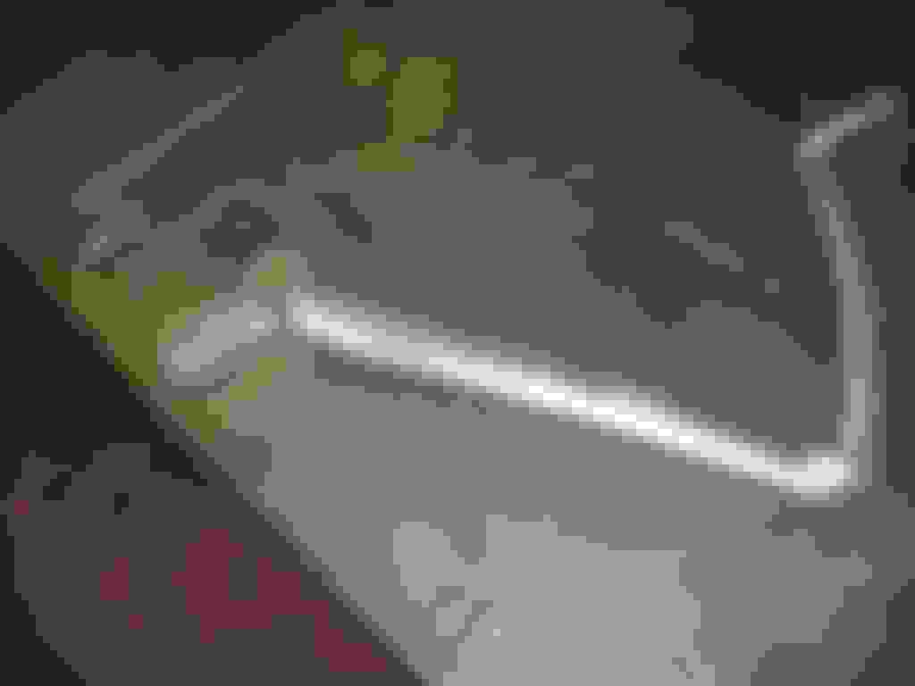
He reversed the front shocks to behind the axle and had the steering linkage mounted in front of the axle.
This is the left front shock and shows the reversed shock bracket.
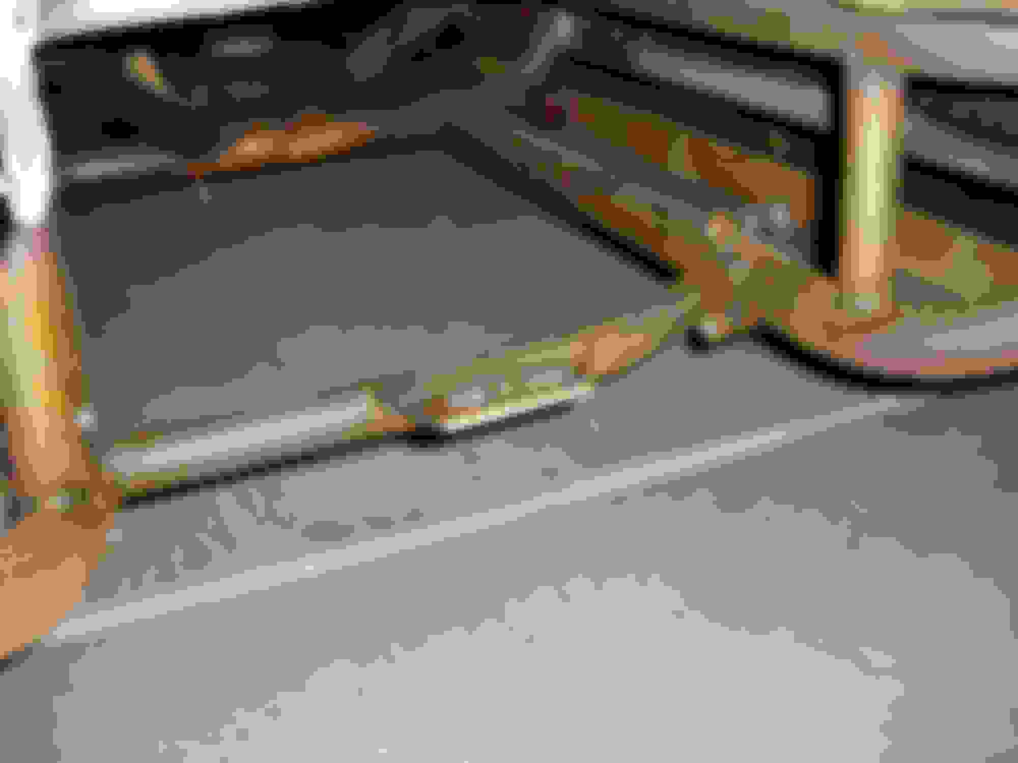
With the smog motor 302 removed, this is what the steering box and linkage looked like. The tube behind the axle is the tube motor mount.
There was some damage to the frame rail that needed to be fixed.
Needless to say this modified steering and suspension would NOT have worked and had to go, which I removed. The rear suspension was stock and unmolested.
I sold off the smog motor 302 and C4 as I wanted to go a different direction with the power train.
Another very interesting build report. Thank you for sharing. I also did a lot of explaining as to how my project was taking so long but after a while I realized most of us here have been down the same long road. Please keep us posted on how it's coming along. And tanks for lots of photos. We love seeing the project. But that steering box you inherited has got to be the ugliest contraption I've ever seen.
Yes, I have spent a lot of time fixing surprises from POs. But even more time revising things after seeing what others are doing here on FTE. Stay flexible.
To continue with updating this thread to where the truck is at in 2017, here are some more pictures.
The PO modified front suspension had to go as it would NOT have worked. I decided to go with an independent front suspension for a smoother ride. I've ridden in old trucks with parallel leaf front suspensions, even ones that were "fixed" to be smoother and I did not care for the ride. I also had to consider my wife's bad back and needed to get the smoothest ride possible. I read the information available here on suspension upgrades and chose to go with the Dodge Dakota front suspension from Industrial Chassis.
Here is a picture of my frame with the old front suspension and Ford 302 and C4 removed. I also removed the spring brackets. The styrofoam piece is to protect my old knees from the sharp corners on the frame.
This is a picture from the Industrial Chassis site with the Dakota IFS installed with the stock control arms.
Steve at Industrial Chassis installed the Dakota IFS kit in August 2009 for me. My install is the last of the Generation 2 kits, and since then he has made improvements to his kits. I am using the stock control arms on my truck.
For the rear suspension, I wanted to keep it simple and keep a parallel leaf rear suspension. I did not want to use the stock springs as I have never known a stock set of springs to be able to give anything close to a "smooth" ride. Again I had to consider my wife's bad back if I was ever going to get her to ride in the truck. I chose the Classic Performance Products (CPP) 4856RLK.
It lowers the truck slightly and clears out the space on either side of the driveshaft by relocating the shocks to a more vertical position behind the rear end housing. You have to remove the stock Ford spring brackets which is easy. The replacement spring brackets use the stock rivet holes so it is almost a bolt on.
Here are some pictures I have of the kit install. I don't have many of this part of the build. The rear of the truck with the stock rear end and springs in place. Yes, that is an 8BA flathead on the engine stand in the other part of the garage.
The rear of the frame with the rear springs and brackets removed.
Here is a picture with the rear leaf kit installed with the Ford 9 inch housing partially installed. It also shows the 4X4s and casters which I used to be able to move the truck chassis and cab around.
This picture is from 2016, the previous ones are from 2009. The house is different because we moved from Mesa to Tucson in 2009 when I had to change jobs. Truck projects get put on hold because life happens. This one also gives you some hints about some of the other changes which have been done. More detail on those in posts to come.
To continue with the updates to catch up to 2017. In August 2009 I took the frame and cab to Industrial Chassis in Phoenix to have them install one of their Dodge Dakota independent front suspension kits. This was the last one of their Generation 2, before they made some improvements. I chose the Dakota IFS as it is a beefier suspension made for a truck and it has a very smooth ride. Since my structural welding skills are extremely suspect, I had them install the kit and do some other frame modifications.
Industrial Chassis, did some frame straightening and boxed the frame from just behind the front cross member to the back of the cab.
The PO had butchered the stock center cross member and it needed to be replaced. The plan back then was to install a Ford 7.3L Powerstroke diesel and 4R100 automatic trans. I had the shop install one of their tubular cross members to replace the butchered center cross member and to stiffen up the frame.
Pictures of their work.
Here is the Dakota front cross member and boxing installed. You can see the tubular center cross member just under the cab. It goes all the way to the back of the cab.
Another view of the Dakota cross member. Note the lower control arm uses two frame pivot points.
This is the right frame rail. You can see the adjustable transmission tube cross member to the right in the picture. It has a dog leg bend so it is easier to remove.
When Industrial Chassis welded in the Dakota front cross member, they made sure to preserve the frame stamped in serial number on top of the right frame rail. That was necessary to preserve my 1948 Arizona title.
Here is a more detailed shot of the new tubular center cross member with the adjustable, removable transmission mount.
That is all for now with more updates and build pictures yet to come.
No, I'll use a single length driveshaft. I discussed with Industrial Chassis if we would need to modify the rear tube of the tubular cross member for clearance and they said no. The driveshaft will need to be no larger than 3 inch diameter. I have the stock drive shaft and I may be able to have it modified if it is long enough. If not I'll have a new one fabricated.
In 2009, while the truck was at Industrial Chassis for the Dakota IFS install work, I had them do some additional frame modifications to be able to install a frame mounted power brake booster.
Since the plan at that time was for a 7.3L Powerstroke diesel, I wouldn't be able to use a vacuum powered brake booster. That dictated the use of a hydraulic brake booster powered by the power steering pump or what's commonly called a hydroboost power brake system. Steve modified the stock brake pedal and added the frame mounts to use one of the CPP hydroboost kits. In order to install the hydroboost, it had to be mounted on the outside of the frame rail with a shaft passing through the frame to the brake pedal. This required the removal and replacement of the left front cab mounting bracket. He also had to fabricate a splined shaft for the brake pedal.
Here are the pictures of that work.
This is the computer model of the new cab mount and hydroboost mounting bracket.
This is the finished bracket mounted on the frame rail with the hydroboost bolted to the bracket. You can see the new cab mounting location. This is also a good detail shot of the new tubular center cross member with the adjustable and removable transmission mount.
Backside view of the new frame bracket with the hydroboost installed.
This is the stock brake pedal before it was modified for the splined insert for the shaft to actuate the hydroboost.
Modified brake pedal with the splined insert and set screw installed.
The splined shaft runs through the frame rail in a steel tube sleeve welded to the frame rail and the boxing plate on the inside. The shaft rides in Oilite bronze bushings in the sleeve.
Finished brake pedal shaft with the actuator arm for the hydroboost welded to the end.
The brake shaft actuator arm is bolted to the hydroboost with this shouldered bolt, sleeve, Bellville washer and the Oilite washer.
Shouldered bolt and washers bolted to the actuator arm and hydroboost.
Inside view of the frame rail with the brake pedal and the cab installed. You can see the sleeve through the frame rail positions the brake pedal in the cab.
One last view of the assembled hydroboost on the outside of the frame rail.
The master cylinder is installed on the aft end of the hydroboost unit. You can use either a Corvette master cylinder or a custom one from CPP. I chose to use one of the custom ones from CPP as it has a built-in brake proportioning valve so there would be a cleaner installation with one less part to buy. I chose this one.
I like the the master cylinder from CPP. If you have trouble with the hydro boost you could also add an electric vacuum pump. For years now gasoline engine powered cars and trucks that use VVT, variable valve timing, use an electric vacuum pump because of low manifold vacuum. The one that is used on Jeep Wranglers is compact, rugged and readily available (Amazon.com) but there are many others.
 01-26-2017, 09:25 AM