Upgrading 1984 E350 dual tank system
#1
Upgrading 1984 E350 dual tank system
Hello all. I have a 1984 E350 Holiday Rambler Ambassador motorhome with dual tanks, a 460, and a 750 cfm Holley. My fuel pumps currently only work when cranking. My oil pressure switch is jumped. I would like to upgrade my current system but I need help understanding it.
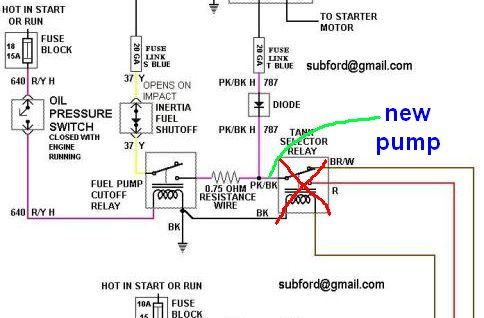
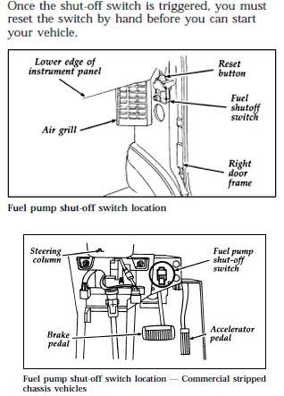
I bought a Carter fuel frame mount fuel pump, and want to run this one pump for my system. It should be adequate. Can I use the stock switching valve? From what I understand, pressure from the tank is needed to operate the valve. What are the 5 wires that go to the tank valve switch for? Also, where is the location of the inertia switch, fuel pump relay, and fuel pump cutoff relay? I do not trust all the jazz going on in this system.
I bought a Carter fuel frame mount fuel pump, and want to run this one pump for my system. It should be adequate. Can I use the stock switching valve? From what I understand, pressure from the tank is needed to operate the valve. What are the 5 wires that go to the tank valve switch for? Also, where is the location of the inertia switch, fuel pump relay, and fuel pump cutoff relay? I do not trust all the jazz going on in this system.
#2
Hi brendo613,
here might be a great place to start:
https://www.ford-trucks.com/forums/1...lem-460-a.html
See if that helps and post back. jim
here might be a great place to start:
https://www.ford-trucks.com/forums/1...lem-460-a.html
See if that helps and post back. jim
#3
Hi Jim, thank you for that link. I had found that the other day and read through it but I still have some confusion. I want to upgrade my current pump but retain use of the fuel gauges. I need to cut power to the stock pumps but I'm not sure where power goes to them from. Is the source the relay on the driver's side inner fender? Also, what do the wires on the tank switching valve do? There are 5. Thank you
#4
Hi Jim, thank you for that link. I had found that the other day and read through it but I still have some confusion. I want to upgrade my current pump but retain use of the fuel gauges. I need to cut power to the stock pumps but I'm not sure where power goes to them from. Is the source the relay on the driver's side inner fender? Also, what do the wires on the tank switching valve do? There are 5. Thank you
Two questions I have are how are you going to modify the fuel pick up in the tanks, and is the frame mounted pump going to supply too much pressure to a carb-ed system? Subford did the original diagram and may see the post to comment. jim

Single frame mounted pump to replace in tank pumps.
#5
Thank you very much for the detailed response! I had to drain the tanks from old gas and there is sufficient fuel flow through the in-tank pickup even when using an external pump. The new pump I have has a built-in regulator. It's a Carter pump designed for carburetor equipped systems, 4-8 psi if I recall correctly. Weather permitting, this should be a successful weekend endeavor.
I was planning on using only the oil pressure switch as a trigger for a separate relay powering the new pump. Thank you much for your help!
I was planning on using only the oil pressure switch as a trigger for a separate relay powering the new pump. Thank you much for your help!
#6
Thank you very much for the detailed response! I had to drain the tanks from old gas and there is sufficient fuel flow through the in-tank pickup even when using an external pump. The new pump I have has a built-in regulator. It's a Carter pump designed for carburetor equipped systems, 4-8 psi if I recall correctly. Weather permitting, this should be a successful weekend endeavor.
I was planning on using only the oil pressure switch as a trigger for a separate relay powering the new pump. Thank you much for your help!
I was planning on using only the oil pressure switch as a trigger for a separate relay powering the new pump. Thank you much for your help!
#7
Trending Topics
#8
MOST of the time, it is under the dash on the passenger side kick panel, in a cutout at the top.
Cargo vans it is under the dash, driver's side, to the right of the steering column.

#10
Owner Manuals | fleet.ford.com
I just cut/pasted 2 pages together in one graphic. I used to teach owner's manuals but on jet planes, not vans.

jim
Thread
Thread Starter
Forum
Replies
Last Post
basicjim
1980 - 1986 Bullnose F100, F150 & Larger F-Series Trucks
10
07-12-2017 05:34 PM
89f150mike
1987 - 1996 F150 & Larger F-Series Trucks
8
06-29-2006 10:26 PM
1988F150
1987 - 1996 F150 & Larger F-Series Trucks
2
04-18-2002 03:41 PM


