When you click on links to various merchants on this site and make a purchase, this can result in this site earning a commission. Affiliate programs and affiliations include, but are not limited to, the eBay Partner Network.
I wanted to say I appreciated @projectSHO89 posting the wiring diagrams for the Headlight Switch wiring diagrams in Post #14. I have now been able to rule out the Headlight Switch. The switch operates as expected based upon continuity/resistance testing.
ISSUE: 2003 Powerstroke 6.0 L Lariat SuperCrew (170K miles). I have no low beams and no high beams. I do have flash/passing (high beam) functionality. I do not have the optional DRL feature. I do have auto lights and fog lights features - auto lights do not work but fog lamps do work. I do have power to the Headlight Switch via the Red/Yellow striped wire - 12V. All exterior lamps illuminate. Signals operate, brake, backup and parking lamps all illuminate.
I pulled the 9007 headlamp bulbs & tested both high beam and low beam spades for continuity and both bulbs demonstrate proper continuity for both high and low beam spades.
Somewhere around the 100K miles mark I lost my headlamps. Prior to losing the headlamps, there was intermittent ON/OFF functionality of the headlamps associated with the tilt wheel until the headlights finally quit operating. From what I can remember, I believe replacing the shift lever (handle) resolved the issue (as there was an exposed wire in the shift lever (handle) and the headlamps worked again.
I suspect the issue resides somewhere w/in the steering column or below the steering column (under the dash) as during this recent episode the same problems began to appear - based upon position of the steering column using the tilt wheel lever, the lights would either be ON or OFF - depending on the position of the moon relative to the Earth's rotation - IOW, another electrical gremlin (conundrum).
What I can't recall is what I did to fix this issue @ 100K miles. I thought I replaced the steering column RH-side shift lever (handle). I can't recall if the TOW feature quit or not and that was the reason I replaced the shift lever (handle) or it was (in fact) a short in the wiring of the shift lever (handle) which caused the headlights to stop illuminating.
I do have the shift lever (handle) removed and I can clearly visualize chafing and an open wire where the black wrapped wire exits the bottom of the shift lever (handle) - I believe it appears to be the brown wire inside. None-the-less, it is chafed and I can see an open bare wire.
As I was trying to visually trouble shoot wires under the dash, I do recall being up under the dash negotiating the placement of (as I recall) that larger yellow wrapped wire loom. I just can't recall why I was up under the dash but I know I was routing a wire at some point in time around the 100K miles mark for some reason - I suspect it might have been the headlights but I just can't recall.
I pulled the relays (under the hood) and the two smaller fuses, sprayed the male relay spades and the female spade receptacles w/ contact cleaner and reinserted the relays & fuses. Perhaps a coincidence (or not), my key tumbler has been acting up, and there have been occasions recently (nearly the same timing as when the headlamps stopped illuminating) where I could not turn the ignition tumbler at all. This has been occurring on numerous occasions. I'm going to R&R the key tumbler regardless of the headlights issue as this tumbler is not operating/functioning correctly.
NOTE: I have NO POWER at the fuse panel for fuse numbers 46 & 47. Yet, I do have power at the headlight switch on the red & yellow striped wire.
I'm perplexed at this point.
Any suggestions would be greatly appreciated and thank you for reading my issue.
Fuses 46 and 47 are fed by the multi-function switch in the steering column. So that points to the problem as probably being in the steering column like you suspected. The red/yellow feeds the multi-function switch in the column.
Fuses 46 and 47 are fed by the multi-function switch in the steering column. So that points to the problem as probably being in the steering column like you suspected. The red/yellow feeds the multi-function switch in the column.
I tested the Red/Yellow-striped wire contained w/in the connector which plugs 'into' the Headlight Switch and the Red/Yellow-striped wire has 12V. I'll have another look at the steering column wiring looms but I can't figure out why I'd have power at the Red/Yellow-striped connector feeding into the Headlight Switch if the MFS feeds fuses 46 & 47. How is it I'm getting power to the Red/Yellow-striped wire in the connector at the Headlight Switch? Unless that is a different Red/Yellow-striped wire (unlikely)? I would think the power goes from the MFS down to the fuses and then into the connector at the Headlight Switch? I can't get my head wrapped around it quite yet. Thanks for the response.
After reviewing a little more information I came to the realization that what some refer to as the Multi Function Switch (MFS), others (including automotive parts supply houses) list the item as the Dimmer Switch, others list it as the Turn Signal Switch, etc. That in itself was confusing to me.
Power for low and high beams goes through the headlight and dimmer switch. Flash-to-pass, goes around the headlight switch, straight to the dimmer. It still can be either part. With the headlight switch in the "on" position, check for power at the Red w/yellow stripe wire at the headlight switch. If you have power there, it's a bad dimmer switch. If there is no power, then it's the headlight switch.
Yes, in fact, it was the MFS I replaced at ~100K miles (the last time my headlights went out). The fact it is sometimes referred to by different names often makes troubleshooting confusing, but I at least now have a direction to further troubleshoot. The fact I couldn't recall what I did to repair this the last time it occurred hasn't helped me much!
So, if I'm following this, I'm thinking/suspecting/considering the power which feeds the MFS (for headlights) routes in this direction: (1) 12V to the Headlight Switch > (2) 12V to the MFS > (3) 12V to both fuse 46 & 47 > (4) 12V to both LH headlamp & RH headlamp.
It's possible there exists one or two relays under the hood for the headlamps (I've read mixed reviews/opinions regarding headlamp relays on the 2003 F250) and I don't have the wiring diagram. Yet, if there was one or two relays, they would sure be located after the fuse(s) 46 &/or 47.
I'll pull that MFS this morning and examine the wiring loom and connections to/from the MFS. It would be sweet if anyone knew of a continuity/resistance test to perform on the MFS itself. One more cup of coffee and out into the man-cave.
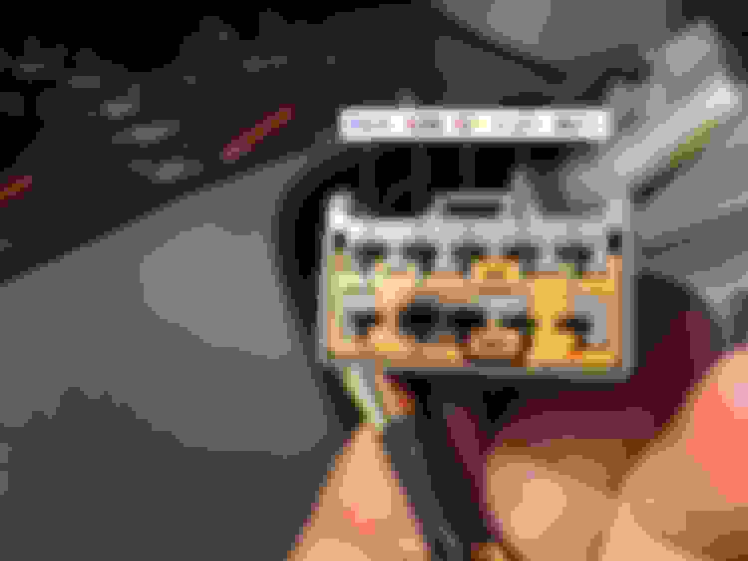
I am suspecting I've found the culprit/issue - faulting MFS. Therefore, I'm cutting my losses right now & ordering a new MFS. I will create a new thread or find a previously created thread w/ a more appropriate title and move my images and issue into that thread so as to benefit others w/ a similar issue. This is the 2nd MFS I have replaced on this 2003 Ford F250 vehicle (170K miles). I don't recall if I replaced this MFS with a part purchased through my Ford dealership or not. In any case, the current MFS is faulty, and I am (also) providing an image of the part numbers listed on the MFS. Spade Numbers 8 & 9 are shorted as referenced in the diagrams (below). Norm
projectSh089 - Spade 9 seriously demonstrates overheating but spade 8 demonstrates overheating, as well (more evident when you're visualizing holding it in your hand). Since they both reside next to each other, I highly suspect (w/o a wiring diagram in front of me) both spade 8 & 9 feed fuses 46 & 47. Since I have no power to fuses 46 & 47, I'm suspecting (hoping) I've found the issue. But, you're correct on checking the corresponding connector terminal wires leading into this receptacle. I've previously mentioned, I have 12V into the Headlight Switch. I'll check the connector terminals from the Headlight Switch wiring loom into the MFS to ensure their integrity and continuity/resistance.
projectSh089 - Spade 9 seriously demonstrates overheating but spade 8 demonstrates overheating, as well (more evident when you're visualizing holding it in your hand). Since they both reside next to each other, I highly suspect (w/o a wiring diagram in front of me) both spade 8 & 9 feed fuses 46 & 47. Since I have no power to fuses 46 & 47, I'm suspecting (hoping) I've found the issue. But, you're correct on checking the corresponding connector terminal wires leading into this receptacle. I've previously mentioned, I have 12V into the Headlight Switch. I'll check the connector terminals from the Headlight Switch wiring loom into the MFS to ensure their integrity and continuity/resistance.
Thanks for the follow-up.
Norm
You are on top of the problem, I think you will have it fixed if you replace the switch and possibly the connector. But from reading the above I am still not sure you have a handle on how the power flows through this circuit. Let me run through it just to make sure.
Everything is a circuit, I will start at the beginning, and describe it as power is flowing from + to - (that's a big debate in itself, but don't worry about it, all diagrams are organized + to - power flow).
The power for this circuit starts at fuse #7, 30 amp in the underdash fuse box. From this fuse it runs to the headlight switch on a darkblue/orange wire. This wire "feeds" the power to the head portion of the headlight switch.
Once you decide to turn the headlights on, the switch puts power on the red/yellow wire. The power "leaves" the headlight switch on the red/yellow.
Power from the headlight switch on the red/yellow "feeds" the multifunction switch. You decide if you want high or low beams with the switch. So two wires "leave" the MF switch. Lowbeam power leaves the MF switch on the red/black. Highbeam power "leaves" the MF switch on the grey/orange wire.
The highbeam grey/orange wire feeds fuse #30, 15 amp in the underdash fuse box. Highbeam power leaves this fuse on a lightgreen/black wire and feeds the highbeam part of the bulbs.
The lowbeam red/black wire goes into the underdash fuse box and splits or y's out and feeds both fuses 46 and 47. Fuse 46 feeds power to the left lowbeam on a darkblue/white wire. Fuse 47 feeds power to the right lowbeam on a darkgreen/orange wire.
I think you are on top of it. Like was mentioned, look at the plug that plugs into the MF switch, the two that are overheated. If they look overheated in the plug, then that will most likely cause a poor connection and cause this problem again. If this is a chronic thing with these year truck usually the aftermarket will sell a replacement plug with short pigtail wires that you can splice in to replace the plug. Do some research and ee if it exists. Only other thing to do if they do not look too bad is try and take some needle nose and squeeze the connectors a little bit to get a better connection. If you go too far and you can't get the switch plugged in you can take a small screwdriver and spread them back open a little bit.
Dave - That's an exceptional write-up on the entire power loop with exceptional detail to the wire colors. Thanks very much for that - it's exactly what I was looking for and hoping to find. Spot-on. Thanks for providing the role of the F.30 15A under the dash & the F.7 30A. I had my suspicions, but you've confirmed them. The colors of the wiring right now is of significant importance to me in testing the continuity/resistance. Great feedback.
I've already determined x2 things from on-line research employing Ford (Motorcraft) part numbers for the MFS. (1) There has been an update to the Part Numbers by Ford Motor Corporation for these switches (at least these switches which were used on this model year of F-250 - mine is the earlier 2003 F-250 diesel). I cannot confirm, but I suspect (hope) the new Part Numbers (which are also compatible with later model Ford vehicles) are (hopefully) of better quality - but hey, nothing more than a guess. (2) I have, in fact, already researched pigtails/plugs. Pigtails/Plugs are available for these MFS's. If I need one (based upon the integrity of the current connector plug), I'll wait until the new MFS arrives to ensure a new pigtail/plug is compatible w/ the new MFS.
The weather here is miserable & I'd prefer to armchair discuss (at the moment) rather than perform addt'l diagnostics. Tomorrow morning I'll address the integrity of the connector plug.
I am not completely certain regarding the integrity of the MSF connector. Visualizing w/ a magnifying glass after cleaning both #8 & #9 w/ contact cleaner swabs & tiny screwdriver, the metal connectors w/in the connector appear OK. There remains some black charred material which I suspect is from the plastic (I'm hoping) overheating. On the other hand, "if" it's metal there is a chance of shorting between #8 & #9). I'm going to search once again for a MSF connector pigtail.
F.7 30A= 12V DkBlue/Orange to Hdlght SW = 12V Red/Yellow to Hdlght SW with Hdlght SW ON = 12V Red/Yellow from Hdlght SW to MSF connector (Spade #8) = 12 V
I was considering using a wire loop between connector terminals to further test, but I'm not completely certain I'm going to gain much confidence in troubleshooting the connector w/o risk of cross-feeding. So, onto looking for a connector pigtail and awaiting the arrival of the new MFS which will be here Wednesday.
agreed. reusing that connector is only a guarantee the new MFS will cook very shortly.
i would also look into finding out what is causing it to overload and burn up.
is there added lights or aftermarket lights on the circuit drawing too much power?
i removed the load on hte light switch and MFS by adding relays to the headlight circuit. now with the relays, the main power for the headlights comes directly from the battery, with the headlight switch and MFS only powering the relays.
Probably the fact it is a defective switch. Switches often times go bad without ever having been overloaded. They fail internally - sometimes as the result of inferior wire, inferior craftsmanship, etc. which might cause them to overload/overheat. That is just a pure simple fact. I didn't make the switch. I don't know the materials used to manufacture the switch.[/QUOTE]
Originally Posted by tjc transport
...is there added lights or aftermarket lights on the circuit drawing too much power?
No.
I appreciate the comments regarding purchasing a new connector which I have already previously stated (see above) I am researching to find the correct one.
I will say, just because a connector demonstrates some visual discoloration that is not in itself sufficient evidence to indicate the connector is bad. The connector has absolutely nothing more than a wire connected to piece of metal in each hole. That is all. There is absolutely and unequivocally nothing more in the hole than a piece of metal w/ a wire attached to it. But, I do appreciate your comments.
the problem is the connector to switch pin itself is loose. this causes heat, which in turn causes the discoloration and melted plastic.
over time, the heat transfers to the switch which then burns too .
the ford headlight switches were about at their limits for current draw for many years, and adding any lights to the circuit would overload the switch causing it to burn up at the pigtail connectors.
every vehicle i have worked on after 86 model year has had issues with headlight switches overloading after adding snow plows and their lights to the circuit. so starting around 92 or so i automatically just started adding relays to the headlight circuits once they came in with burned pigtails or switches.
 04-22-2016, 10:55 AM