When you click on links to various merchants on this site and make a purchase, this can result in this site earning a commission. Affiliate programs and affiliations include, but are not limited to, the eBay Partner Network.
Thought I would document how I dug the EFI circuits out of a 90 F150 harness.
Could go many places on this site. Mods, if it fits better in Electrical, or the bricknose/OBS forum, please feel free to move it. Thanks.
EECIV Standalone Wiring Harness
This will document the fabrication of a standalone wiring harness for an EECIV Speed density EFI system for a Ford V8. The process will convert the underhood wiring harness found on an 89 through 91 Ford F150 pickup by removing all the circuits not involved with the EFI system. This would be desirable for vehicle conversion purposes where the vehicle was not originally equipped with an EFI equipped Ford V8, or for the purpose of running an engine outside of the original installation.
The 88 to 91 F series truck harness was chosen for it's wide availability and clean design. Ford installed EFI in many configurations and a similar process may be used to build a standalone harness with other than the application described here, however details will differ.
The Ford truck was one of the most popular applications of the Windsor style Ford V8 and also the longest production run of this platform. It was offered through 1996 in the F150 platform and 1997 in the F250HD and F350 platforms. The 5.0 was offered in the Explorer till 2001 and was equipped with EDIS ignition, MAF SEFI and EECV with OBDII. All gas V8 EECIV SD applications are similar electrically, so they can be considered as compatible although ECU calibration may differ. MAF applications will require additional considerations to support sensors and SEFI and that is outside the scope of this project.
Ford started to install EFI on the Windsor V8 in 1985 as an option for the 5.0l F150. It became standard in 1986. The 5.8l Windsor engine remained carbureted through 1987. The 85/86 vehicles used an add on type of harness to install the EFI components. It placed the ECU and connector in the cab, under the dash near the center of the vehicle with the harness running through the firewall behind the LH cylinder head. 87/88 saw the harness integrated with the ECU mounted inside the cab behind the LH kick panel with the connector passing through the firewall. 89 through 91 saw a further refinement with the engine harness conveniently and neatly routed to 4 color coded 8 pin round connectors located on the LH inner fender. 92 and up used a single square connector located towards the back LH side of the engine. The 88 through 91 harness was chosen for this project on the basis of it's clean, organized appearance.
The engine harness must be removed in it's entirety from the donor vehicle. The harness routes from the LH firewall, where a circular connector passes through the firewall to the dash harness and the rectangular ECU connector attaches through the firewall to the ecu, passing along the LH fender and crossing to the RH side along the rad cradle tucked in behind the cooling and A/C rads, (if equipped). It then runs to the starter solenoid and HEGO connector located on the RH fender and continues to the HVAC and finally to the MAP sensor which is mounted to the upper corner of the HVAC plenum.In all, the finished harness will be 13' long. The main connector and the ECU connector are held with a 10mm bolt through the center of the connector. There are grounds at the cowl end of the LH fender and two along the run across the rad cradle. The only thing you should be cutting here is any cable ties. All wires, connectors and grounds must be unplugged or unscrewed. Remove the cruise control servo, (if equipped) to aid in access. There are two banks of four circular connectors near the firewall connector on the LH inner fender, one bank making connections from the engine bay harness to the under body harness and the other bank handling connections to the engine. Separate all the connectors. Disconnect the windshield wiper motor. There is a bank of relays attached to the bracket for the coolant recovery and washer tanks.Remove and save the relay bank. Note the relay holder/shield is rather fragile and often broken. Remove the tank bracket to allow removal of the wiring harness from the vehicle. Remove the grill and unplug the horns as well as the DRL module if equipped. Disconnect all the wires from the starter solenoid and remove all connectors from the HVAC. Remove and save the MAP sensor and bracket which is located on the upper inner corner of the heater plenum at the firewall. Disconnect the headlights and turn signals. Unbolt the top bolts for the cooling and A/C rads. Tilt both the rads back to allow removal of the harness.
MAP sensor location
ECU and engine connectors
With the harness removed from the vehicle, you are ready to prep it for modification. This involves cutting open the wire bundles. This is tedious and dirty work. The harness will be wrapped in flexible split conduit and tape. 25 years of dirt and grease will be on this covering. Technique for removing the tape and conduit is variable, but the usual method would involve slicing the tape with a sharp utility knife, locating the split in the conduit and pulling the conduit off. Be careful not to nick the wires with the knife and take appropriate safety precautions against cutting yourself as well. You will encounter vinyl tape as well as cloth tape and possibly tarry substances within the wire bundle.
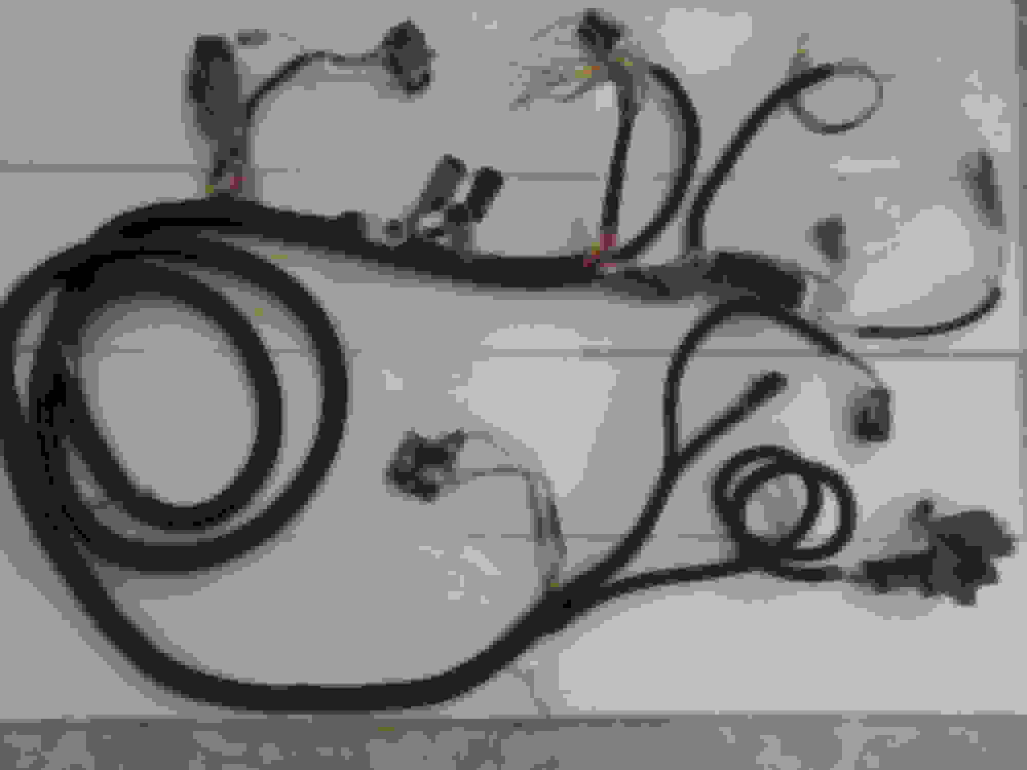
Harness as removed from 90 F150.
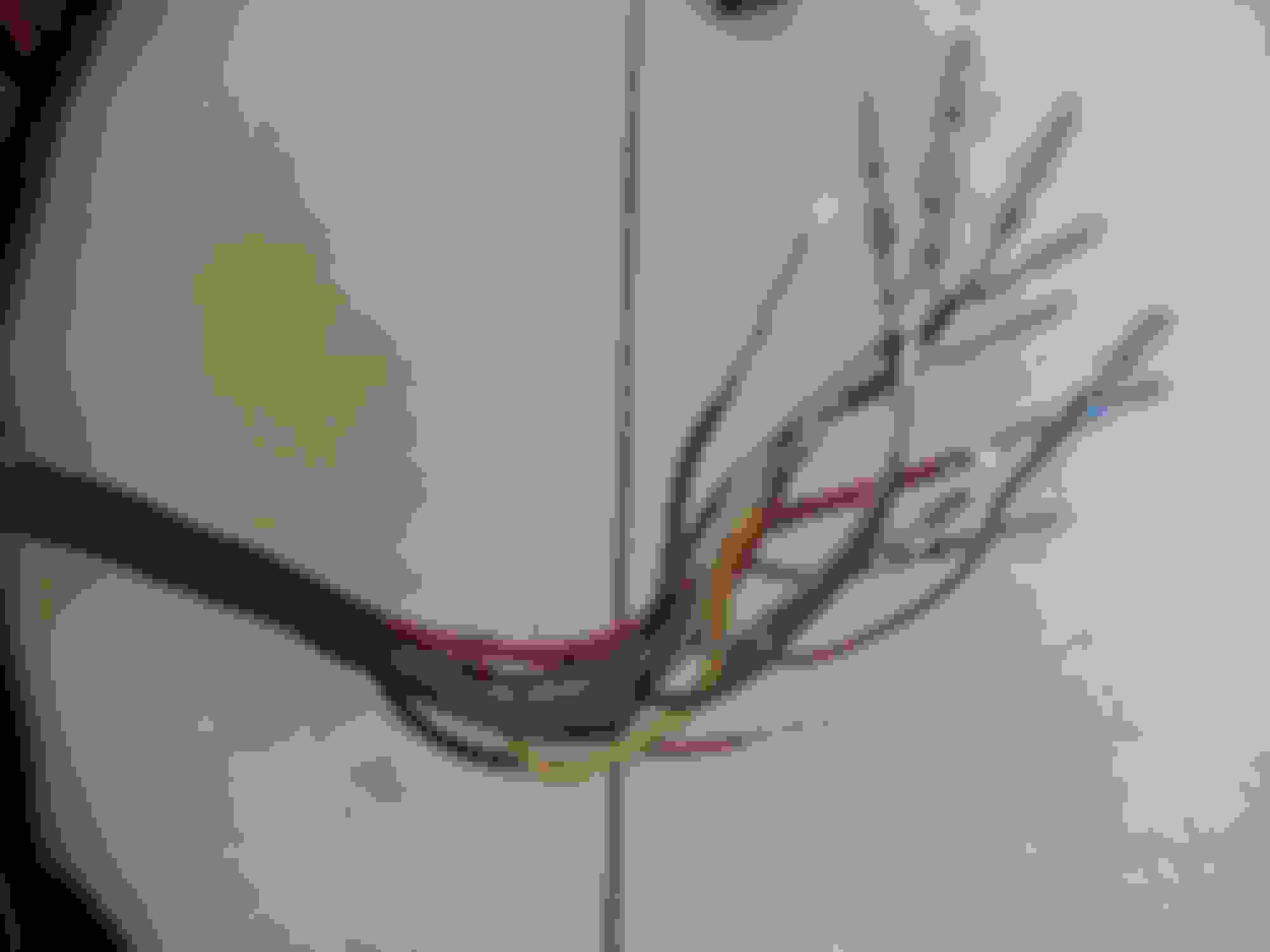
Opening the wire bundle
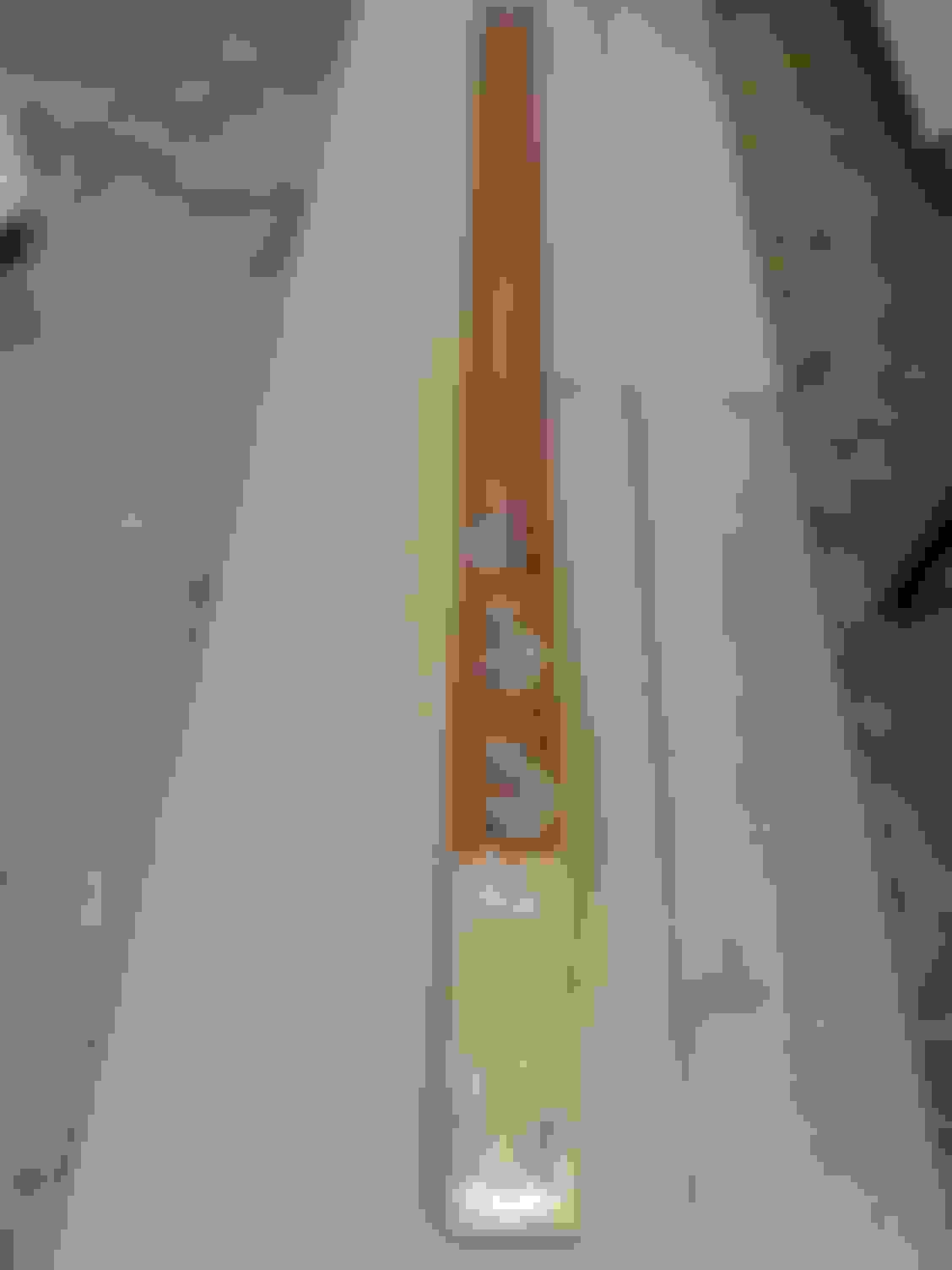
It is important to maintain order and avoid distractions when you have the bundle open. It's easy for the harness to morph into a frustrating ball of snakes. Give yourself plenty of room and lay the harness out in a line. I used a 2X4 and some dollar store tool hooks to make a jig that I could tie the harness to. Really helps maintain order. Also got some velcro cable ties to help with separation and bundling.
Harness jig
Holding the harness in the jig.
Once the wire bundle is exposed, you can begin to isolate the EFI circuits from the other vehicle circuits. It will be extremely helpful to stretch the harness out on some sort of rack to minimize tangling as you deconstruct. You will need a strategy to separate the circuits you will keep from the circuits you will discard. There are a number of challenges here. First, identify what you must keep. In this case, the ECU connector, the four circular 8 pin engine connectors and the MAP sensor connector will remain undisturbed. The individual wires will inevitably run in a path that loops through other wires, preventing you from cleanly and logically dividing up the circuits. When the wire terminates in a connector, it often closes the loop making it impossible to separate the wire groups. Rather than cutting the wires, it will be a good practice to unpin the connectors.
Fortunately, the design of the Ford electrical connectors make this easy without special tools. The connectors contain a red insert that locks the terminals into place. With this retainer removed, there will be a small tab locking the individual terminals into the plastic plug body which can easily be released with a thin pick or flat screwdriver and the wire and terminal can be pulled out through the rear of the connector body. Removing this locking insert can be accomplished by fishing it out the mating side of the connector. There is often an access hole in the back or side of the connector body that allows you to push the insert out with a thin punch, or a stiff wire. Sometimes you may have to pry out a rubber weather sealing insert to access the release hole and remove the wires.
Firewall connector with retainers removed
Removing pins from the firewall connector
It is best to work with one wire at a time when untangling the circuits. Sometimes a wire you wish to keep may be restricting the removal of a group of unneeded wires. Unpin the wire, thread it back through the wires you wish to remove and repin it to it's original location when the path has been cleared. One significant exception will be the circular firewall connector. This connector will not be reused and is the originating point for most circuits. It is a good strategy to unpin this connector completely as this will free up most circuits allowing you to remove them one wire at a time.
Cutting wires should be minimized. Every circuit for EFI in this harness can be isolated without cuts or splices with one notable exception. This can be found in the black tarry lumps found within the wiring harness. You will notice several wires of the same color terminating in these lumps and if you cut them open, you will discover a spot welded splice. Of particular interest is the black wire splice which is one of several grounds. Cut the wires free from this splice. Any necessary grounds can be reconnected later. Keep the wires as long as possible. There are other splices of different colors that should be left intact, notably the heavy gauge red/green stripe wire which is the fuel pump power circuit. There also is a splice made with heatshrink tubing near the circular connector and the ECU connector with a green/yellow stripe. This is the power relay control wire. Another heatshrink splice is found in the grey/black stripe and red/blue stripe circuits, both lighter gauge wire. They are the VSS+ and crank circuits respectively These functions are used in multiple places besides the ECU and will be dealt with later. Another wire of interest will be found in the black ground splice that will be cut open and this wire is pink/orange and is VSS-. For now, pair it with the grey/black VSS+ wire.
Main power and ground wires run along the length of the harness. There are two black/white stripe ground wires which run to the ground removed on the RH side of the rad cradle. There is a heatshrink splice to a third ground wire and a short heavy gauge wire terminating in a lug that bolted to the rad cradle. Do not disturb the splice, trace out the third ground wire and unpin it. You may wish to reuse this ground connection later. Isolate the ground wires all the way back to the ECU connector. Main power is supplied via the heavy gauge yellow wire. Fuel pump power is supplied by a lighter gauge yellow wire. Both power feeds are protected by individual 20 gauge fusible links and are tied together with a third red wire also protected by a 20 gauge fusible link to a splice to a single wire and eye end connected to the battery terminal at the starter solenoid. Cut the splice apart leaving the fusible links connected to their respective power feeds and isolate the two yellow wires all the way back to the power and fuel pump relays. There is an additional yellow power feed of medium gauge that runs with it's own fusible link all the way from the solenoid to the firewall connector. You may wish to use this circuit along with the ground wire discussed earlier as a power feed to the user connections which will be located approximately where the firewall connector was removed.
This would also be a good opporunity to isolate the red/blue stripe solenoid control wire with the push on angle boot. It can be isolated back to the splice located near the engine connectors. There is a branch of this circuit formerly paired with VSS+ for the cruise control connecter. This will be rerouted and reused.
The MAP connector circuits are next. They can be isolated right back to the ECU connector. They may interweave with other wires, so this will be an opportunity to unpin and repin the MAP connector 1 wire at a time if possible so you can untangle the wires individually. If you must do all 3 at once, make a note of where each wire is positioned in the MAP connector and reassemble in the correct order at the first practical opportunity.
The HEGO circuits also run in this path. Isolate the orange, purple/orange and grey/blue stripe wires back to the splices located by the engine connectors. They terminate in a 4 pin circular connector that should be repinned in the same order. This connector also contains a black ground wire. In some harnesses, there is a second HEGO connector located near the firewall connector. In this harness, it is present, but capped.
There are 2 more wires running the length of the harness that are of interest. There is a heavy gauge black/yellow stripe wire running from the white engine connector to the A/C system. Unpin at the A/C end and isolate back to the white engine connector. Another A/C circuit is the purple wire. Unpin and isolate back to the ECU. Repin with the correct arrangement to the circular 3 pin connector for the A/C circuits. The third wire in this connector is a ground.
You can start removing the unneeded circuits. All that remain in the long run across the rad cradle can be disconnected and discarded. Headlight and horn circuits are no longer required, same for wiper. All the rear vehicle wiring can be disconnected and discarded.
There is a short ground circuit connected to the ECU connector and running to the upper rear corner of the LH fender. This was unbolted during dissassembly and will remain.
You will eventually end up with a harness starting at the ECU connector followed by 6 wire bundle breakouts in the first 3' and the long run of power and sensor wires which ran across the rad cradle. The first breakout will be right at the ECU connector and consists of the short ground circuit and the VSS+/- wires. The 2nd breakout consists of the LH HEGO connector and the wires formerly terminated in the firewall main circular connector. There are 11 wires of interest here, only one of which was not originally part of the firewall connector. List follows;
All wires light gauge except as noted
Heavy gauge red/green Fuel pump power Switched by fuel pump relay
Medium gauge green/yellow stripe Power control Controls ECU power relay
Blue/yellow stripe MLPS Neutral/clutch to ECU
Pink/green stripe CEL light Instrumentation
Red/white stripe Temp gauge Instrumentation
White/red stripe Oil gauge Instrumentation
Black/yellow stripe A/C clutch To white engine connector
White/pink stripe Tachometer To white engine connector
Purple/orange stripe Hot in run (fuse 5) To RH HEGO connector
Red/white stripe To LH HEGO connector (not used)
Blue/red stripe Crank solenoid control (Formerly paired with vss+ @ CC)
There are two more wires optional at this breakout. One will be battery power (yellow) and the other will be ground, (black/white stripe). They are both of medium gauge and run from the solenoid and rad cradle connections. They are not essential for EFI operation, but may be a convenience, particularly in a stand alone configuration.
The 3rd breakout is the grey engine connector. Following 4th breakout is 2 engine connectors, black and brown followed by the 5th breakout which is the white engine connector. The 6th breakout is the power relay, fuel pump relay, and test connector. The remainder of the harness is a long run of wires that ran across the rad cradle to the RH side of the engine. There is a breakout for the main ground wire about 5' from the end, followed by the HEGO and solenoid/power connections 3' further and finally, the A/C connector and the MAP sensor at the far end.
Now it is time to reassemble the harness. First, you need to restore some grounds that were cut. At the MAP sensor end of the harness, there are ground wires to the HEGO and A/C plugs. They can be joined and spliced to a single wire running back towards the main harness ground which was removed at the rad cradle. Next is a pair of grounds at the main power relay and the brown engine connector. They too can be spliced to a single wire and run towards the grounds at the ECU end of the harness. The connections should be soldered and taped. It is important to select wire that is of the same quality as the original wiring and I did in fact salvage black wire removed from other parts of the harness for this purpose. I even managed to save one of the original ground connection lugs. The gauge of the wire should exceed any of the individual wires spliced to it.
Ground respliced
And taped
The pink/orange stripe wire for VSS- also may be spliced to retain the connector. Originally, this was a ground, but I leave it isolated so VSS may be connected as required external of the harness.
Use quality materials!
When recovering the wires with split loom convoluted conduit, 3/4� should be used for the long run from the engine connectors to the solenoid. The main ground will break out of the conduit along the length. The remaining runs to the HEGO, MAP, and A/C connectors can be covered with 1/2� split loom. Secure the ends of the split loom with a couple winds of good electrical tape. Taping connections vs. shrink tubing is a matter of personal choice, but I prefer a well applied layer of quality electrical tape over shrink tubing. Do not scrimp on materials quality and make sure solder connections are flowed fully and tape wrapped evenly. Wraps of tape can be used to secure wire bundles as required, but do not tape the entire run.
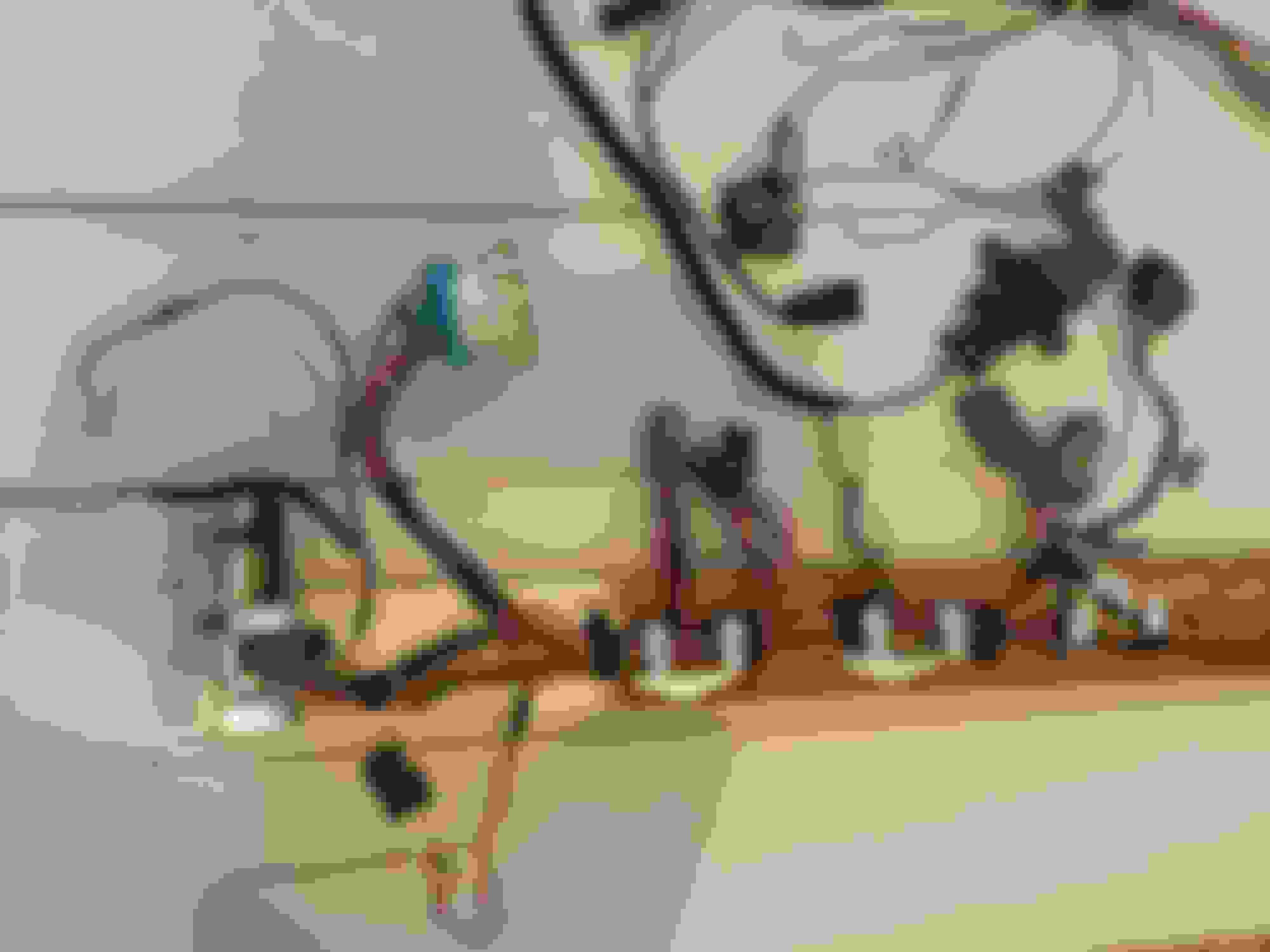
Finished harness
The finished harness will look something like the above picture. Note the MAP sensor and starter solenoid are shown attached for clarity. The other connectors at this end are for HEGO and A/C.
Note the fusible links have had new terminals attached.
You can also see the PWR and FP relays along with the EECIV test connector. This can be reassembled into the relay holder from the donor truck.
User connections
The bundle of unterminated wires originally connected to the main firewall connector. There is a description in preceding text and you will need to attach these to the controls and indicators in your application.
The ECU connector can be seen as well as the unused HEGO connector and the VSS connector. The ring terminals are ground connections which should be made as close to the ECU as practical.
I know this is a year old but I have questions. What ECU do you use? When you say "isolate", do you mean from the bundle? Would it help to get a wiring diagram for the donor
vehicle? This will be my first try at doing this, and I will have some help to do this.
The specific example here was for EECIV, speed density and no transmission control. The ECU wiring is reasonably generic. This harness was from a 5.0 truck and it does not include the engine harness, which plugs into the 4 small circular connectors just downstream from the ECU connector. The engine harness and ECU are specific to the engine used.
I'm using the term "isolate" to describe the process of separating the EFI circuits from the other vehicle circuits like lights, etc. They all run in the same harness and through the firewall connector and the whole purpose here was to make a harness suitable for retrofit into a vehicle that did not have EFI.
Nice work here Ray, lots of people inquire about what is needed to do MAF conversions on these trucks and this write up shows much of what would be involved so it will be helpful there too.
Thanks Ray for the quick reply. I have another question, what does the vss plug into?, and if you don't mind, farther down the line I may have more questions.
In a '90 I think the VSS got signal from the speedo gear that plugs into the trans (2wd) or transfer case (4x4)
I believe it was 1991 that the VSS got its signal from the tone ring/ABS sensor in the rear diff.
There would be a jumper to connect the VSS to the main harness.
VSS is used for a number of functions including cruise control and ABS. The signal is split in the wiring harness and it is sourced from the rear diff in most 87 and up applications. I think the 85/86 trucks used a transmission or transfer case mounted sensor. I could be wrong on applications, any specifics would be welcome.
The VSS is also used with the electronic speedometers in the 92 and up trucks. There is an additional module called the PSOM in these applications. This signal can also perform functions related to transmission control when you get to the 4R70W and E4OD transmissions. It is pretty important to consider this when using the electronically controlled transmissions, but this article was specifically targeted to the 91 and earlier applications without transmission control. There are some E4OD transmissions in 90 and 91 models, but this is a function of the ECM used. Additional wiring is required which is outside the scope of what I have presented here. All can be solved, but I would highly recommend some additional research into transmission control.
A good EVTM, (electrical and vacuum troubleshooting manual) for the specific harness you are working with is highly recommended. Factory publications are best Chiltons and Clymer's provide some generic information, but there is a lot of detail lost, particularly connector pinouts.
MAF conversions are a popular goal and again, I'm going to stress that the example presented is SD. EECIV MAF systems can be found, but they are relatively scarce in Ford trucks. The engine wiring harness includes extra circuits not found in the SD versions.
There likely is a lot more to add, I'm working on a MAF EECV OBDII harness from a 96 Ford F150 at the moment. Will post up details as I progress.
VSS is used for a number of functions including cruise control and ABS. The signal is split in the wiring harness and it is sourced from the rear diff in most 87 and up applications.
...
The VSS is also used with the electronic speedometers in the 92 and up trucks. There is an additional module called the PSOM in these applications. This signal can also perform functions related to transmission control when you get to the 4R70W and E4OD transmissions.
So, could a VSS signal from say an '88 axle be used in conjunction with the '95 harness and E4OD controller?
EDIT: ahh, PSOM is speedo cluster... don't have that, and wouldn't be using it in the '52.
Any rear axle that has the sensor could possibly be used for the VSS signal. The 92 and later trucks with the electronic speedo and the PSOM module run this signal through the speedo head and condition the signal before sending it on to the ECM. To the best of my knowledge, the sensor in the diff is unchanged from 87 through 96 and the pre 92 trucks send the signal directly to the EECIV ECM. I do not know if the later ECM's will work properly with the unconditioned signal, but I suspect they might. There also is an inexpensive speedo calibration module from Dakota Digital that likely may perform the same sort of conditioning. As far as engine functions go, I understand this signal is only used to adjust idle characteristics. If you have an electronically controlled transmission, this signal controls much more.
Does your 95 setup have an ECM connector with 3 or 4 rows of pins? EECIV has 60 pins in 3 rows where EECV has 104 pins in 4 rows and is OBD II as well. The later trucks also had a remote mount ignition module.
I should add in answer to your earlier question about what you may need aft of the firewall, there is an inertia switch in the fuel pump line that is mounted inside the cab, usually on the firewall above the transmission hump on a truck.Same red/green wire as the circuit from the relay and it simply is a series connection into the fuel pump power wire. The system will run without it, but it is an important safety item. Fuel pumps as well need to be the continuous power variety with the supply and return lines to the tank. There should be a fuel pressure regulator on the fuel rail. Current day fuel pump technology did away with the return line and adjust pressure with a modulated power signal. This type of pump and fuel system would not be compatible with the EECIV or EECV ECM. If you are running an OBD II system, you will also need the OBD II test connector located under the dash.
I've paired down the engine harness and clipped a bunch of wires from the power distribution loom. I haven't yet figured out where the VSS comes into play, especially since I don't have the PSOM. I know VSS drives ABS and cruise control (neither of which I will have) but also sounds like tranny control, too.
I just wanted to say I found this helpful. I've read it twice and feel a bit more confident about my project. I have an '84 F150 with worn out 302, And just got a decent 5.0 and harness/ECM from a '92 Bronco.
I hope to weed it down to just the bare minimum. Obviously I'll be dumping the ABS and anything body related (headlights, etc) for just a standalone harness. Is it correct that I don't need VSS if running a mechanical speedo and C4? Also, where does ECU get a crank position from for timing spark and injectors?
That 92 Bronco will likely have an electronically controlled transmission, either 4R70W or E4OD. Either way, the ECM will throw codes if there is no transmission connected.
The ECM will run without VSS. Like I said before, I think it only affects some idle characteristics, but if the sensor is there, (and it is on any 8.8), there is no reason to not hook it up.
The specific example here was for EECIV, speed density and no transmission control. The ECU wiring is reasonably generic. This harness was from a 5.0 truck and it does not include the engine harness, which plugs into the 4 small circular connectors just downstream from the ECU connector. The engine harness and ECU are specific to the engine used.
I'm using the term "isolate" to describe the process of separating the EFI circuits from the other vehicle circuits like lights, etc. They all run in the same harness and through the firewall connector and the whole purpose here was to make a harness suitable for retrofit into a vehicle that did not have EFI.
Hope that helps and good luck with your project.
Need to know what signal is needed for the mlps nutral clutcj,power relay control,, putting a 91 5.0 into a 57 ranchero so I just need to start engine before wiring the car
 02-29-2016, 06:24 PM