When you click on links to various merchants on this site and make a purchase, this can result in this site earning a commission. Affiliate programs and affiliations include, but are not limited to, the eBay Partner Network.
Tachometer differences with engineering numbers...
0 - 4500 RPM with 10, 20, 25, 35 and 45 on the dial.
On the face in the lower right hand corner is: EOTF-17B316-B.
On the back is CB0029 FARIA REVM and near that is CAL with 4 under the A.
At the top [rear], upside down is 6A26 with H(?) above the A.
This tachometer is the "open" type with no plastic housing on the backside.
The 4 terminals are starting at the top left and going clockwise: 1/sig, GND, B+ and GND8.
The instrument cluster from which this came had an electric speedometer [75 MPH] and the light bulb filters were very clear and green [not the normal blue].
0 - 4000 RPM with 10, 20, 30 and 40 on the dial.
On the face in the lower right hand corner is: EOTF-17B316-B.
On the back is EOTF-17360 - BA [printed; rather than embossed].
Under the above number is a Y [embossed and located under the F] and E169 [printed beginning under the 60].
This tachometer is the "closed" type with a protective plastic housing.
The 4 terminals are starting at the top left and going clockwise: C, G, B, and 8.
This unit was in a 1980 F700 with 370 or 429 engine. [a very special thanks to Ford F834 for finding this one! ]
0 - 3500 RPM with 5, 10, 15, 20, 25, 30 and 35 on the dial.
On the back is EOTF-17360- DA [printed rather than embossed].
Under the F is an embossed Y and under the 3 is A211 [printed].
The above information came from the rounded portion of the protective covering on the back; underneath that on a flat area was EOTF-17B316-D(?) [not sure of the "D"].
The 4 terminals are starting at the top left and going clockwise: S+, G, B, S-.
This unit was in a 1981 or 1982 F800 with 370 engine and automatic transmission.
None of these tachometers has any indicated yellow or red zones.
Why the S+ and S- on the 3500 RPM tachometer?
Does anyone have additional information regarding these somewhat unusual units?
This is really great info. F150six! There is very little out there on the web regarding these rare tachs. I wish I could contribute, but most of what I know I learned from you. Here are a couple pictures I took of the 4K tach before I sent it to you, just for visual interest.
Did you ever install one of these in your truck? I keep checking the junkyards for additional units. If I find anything interesting I will send it to you.
Wow... 1 picture is worth a 1000 words!
I am getting ready to replace my current 6000 RPM tach with one of these. For the longest, I have wanted the 4000 RPM tach [which you provided!] since with my driving style, the 4.9L engine rarely exceeds 3000 RPMs... more like 2500.
Then I came across the 3500 RPM unit which has 500 RPM increments and thought that would be neat. However, I am puzzled with the S+ and S- terminals and do not want to take a chance of damaging the tachometer. I think the S+ might be the same as "signal" or "coil" and S- might be the same as the 2nd ground used for V8 applications.
I know this tachometer came from a truck with the 370 V8, but it was not running. I do not believe it is for a diesel... all diesel tachs I have seen have yellow and red zones. From what I understand, diesel tachs are triggered using millivolts rather than 12 volts, so I was hoping to get some forum help before powering up these tachometers.
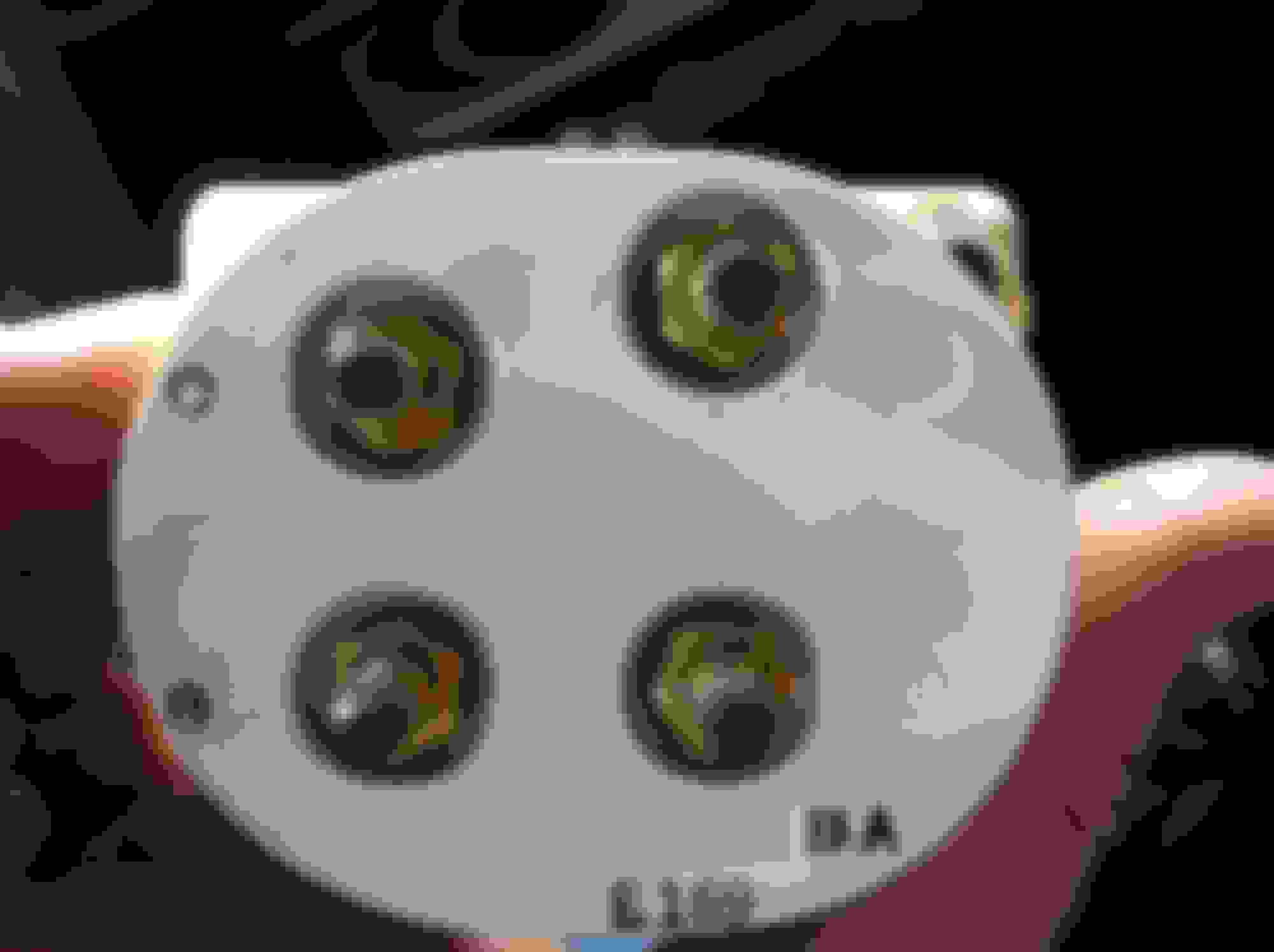
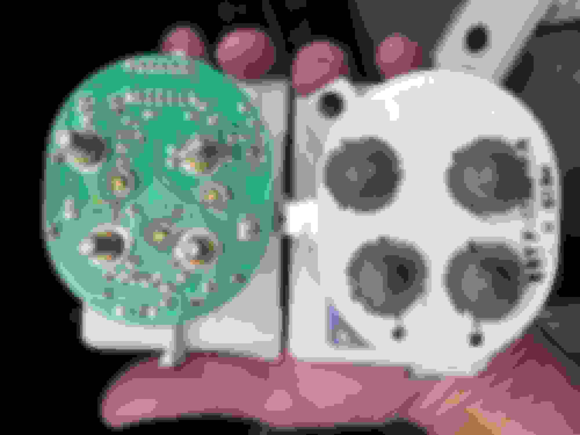
Okay, I may have at least a clue regarding the S+ and S- marks... I looked at my picture of the enclosed style diesel tach next to the open, integrated circuit style diesel tach. The closed style tach has ink stamped marks labeled S+ and S-. The open circuit tach's printed circuit is marked "sig" where the S+ is, and marked "gnd" where the S- is. So S+ appears to be the signal wire from the sender and S- appears to be a second ground... at least for the diesel application.
Okay, I may have at least a clue regarding the S+ and S- marks... I looked at my picture of the enclosed style diesel tach next to the open, integrated circuit style diesel tach. The closed style tach has ink stamped marks labeled S+ and S-. The open circuit tach's printed circuit is marked "sig" where the S+ is, and marked "gnd" where the S- is. So S+ appears to be the signal wire from the sender and S- appears to be a second ground... at least for the diesel application.
That looks like what I have [3500 RPM tach], but there is no yellow or red zone on the face. Ford F834, does the front of the same tach you have pictured have a yellow and red zone?
I do not want to "fry" or damage the 3500 tachometer in any way.
Someone said the diesel tach gets a square wave signal. If so, it is likely to be battery voltage to ground. But the gas tachs get the primary side of the coil, which gets a lot more than battery voltage due to the EMF off the coil. IIRC it runs at least 30 volts with spikes much higher. Unless the diesel tach has some protection built in it might not like the signal off the coil.
That looks like what I have [3500 RPM tach], but there is no yellow or red zone on the face. Ford F834, does the front of the same tach you have pictured have a yellow and red zone?
I do not want to "fry" or damage the 3500 tachometer in any way.
Thanks to you and Gary for helping with this!
Yes, both tachs in that picture are from 6.9L diesel trucks and have the yellow and red zones on their faces... here is the frontal view of those same two tachs...
Edit: the top photo with the dull yellow zone persisting and washed out red zone is the 83-84 "enclosed" style tach, and the bottom photo with the washed out yellow zone and persistent coral pink red zone is the 85-86 "open" (integrated circuit) style tach.
Here's a post from some technophobe. I'm not quite sure what he is saying, but the "50 jolts" bit caught my attention:
Originally Posted by Gary Lewis
Here's picture of the input to the coil, the green wire (DG/Y in the schematics). The trigger is at the point the DS-II module fires the ignition, which means it quits taking the terminal to ground, letting it go up. And the scale is 10 volts per division, with ground being two divisions up from the bottom.
As you can see, the voltage goes above 50 volts positive, swings back negative, then positive, and gradually decreases its swings until it it settles in at about 15v for a bit. (It's going for battery voltage even though there is a resistor in the positive feed to the coil as there's effectively no current and with no current there is no voltage loss.) Then the DS-II box grounds the terminal and the voltage swings and then settles down to ground while the coil charges up magnetically, which is the "dwell". (I don't know why the voltage goes ~15v negative after a bit. Do they use a voltage-doubler to effectively hit the coil with 30 volts?) Anyway, it then goes through that cycle for every cylinder.
My point in all of this is that if the sensing circuitry is voltage sensitive you need to have some protection on it as it will certainly see more than 50 volts. In fact, what my scope shows is actually less than w/o the scope because the scope's capacitance, however small, will tend to dampen the swings slightly. So, were it me, I'd put a 25 volt zener across the input with a resistor ahead of it so it isn't trying to deal with the coil's wrath.
And here's the pic that was supposed to be with the quote:
 08-10-2015, 01:08 PM


 ]
]