When you click on links to various merchants on this site and make a purchase, this can result in this site earning a commission. Affiliate programs and affiliations include, but are not limited to, the eBay Partner Network.
Ok so I am having issues with my GPR not running volts to the big post that engages the glow plugs on. All of the other posts on GPR are reading 12.3v when the key is on and wait to start light is on. Well I guess I want to hook up a push button jumper that I can push while in tuck to get power over to the other post! I need to know the proper way to do this, like where do I hook wires to and such. Thanks
Remove both of the small wires off of the GPR... Turn the key on and use a test light to see which one of the small ones turns on. Reinstall that one. Tape the other one off. Before you say that both of the small wire have 12 v, one does not but is actually showing that the relay is getting lack of ground. If you check it like i wrote, with the key on, one small wire will have power, one will not. IF you reinstall the wire that has 12 v, you will then find that the other small post on the relay will have power but the disconnected wire will not.
To answer the question, hook the small wire with 12v to the relay. The other small post will need to be hooked to a momentary push button switch and another wire from the switch run to a chassis ground. When i had to do it, I ran a 10 gauge wire in the cab to the switch, and the other to the ground under the dash on the right side of the steering column.
I will do that wire test in the morning. Can you explain the hooking up the button a little further. I seem to be lost on that. How will hooking up a wire to the small post get power to the large post that is not getting anything with key on?
This may help. It does not matter than the one pictured is the square bosch type. The description is the same. High current-big wire. low current-small wire
Its a relay... Relays allow large current devices to be controlled by small current control circuits. The big wires are large current wires that feed the glow plugs themselves. The small wires are low current control wires. One small is a keyed 12v power and the other should receive a ground from the pcm to energize the relay, thus supplying 12v high current power to the other large post on the relay to make the relay work. For whatever reason, your truck is not sending the signal to it. It could be a sensor or something wrong with the pcm. A scanner will help you if you have one. There are two relays together behind the fuel filter. You are checking the one that furthest back? The one closest to the front and slightly taller is the AIH relay and rarely energizes.
I used this switch.
http://www.ebay.com/itm/like/271784866540?lpid=82&chn=ps
Its utilitarian but designed for this type control circuit. Most any Napa will have it. You will see it has two phillips head screws on the back of it. Run the wire from the small post that you left empty from the test above to one phillips head screw. Attach it with a ring terminal. Hook the other phillips screw to a good ground. I used the dash ground to the right of the steering column when you take the panel out underneath.
When i had mine installed, i would hold the button until the WTS light went off. Then crank the truck and hold for another 30 seconds on really cold days. Its amazing how long the control system will keep the GPR engaged when it works as its supposed too.
Well, you’re lucky that this issue has occurred in the Summer Months. You have a good amount of time to identify and repair.
I would recommend that the OEM Circuit be repaired rather than altered to activate the Glow Plug Relay. Unless you’re planning to re-create the entire circuit independently of the PCM. Otherwise, you stand a good chance of destroying the PCM with a voltage spike. And, you don’t know how long to activate the circuit.
The WTS Light only illuminates for 1-5 Seconds. HOWEVER, the Glow Plugs remain energized from 1-120 Seconds. And, will automatically recycle as necessary.
Another issue to consider this time of year is the length of time the GP's are on. Unless it's the first start of the day, they may only be energized for a brief period of time. It'll take two people or long DVOM Leads to perform the test.
Electrical problems often can seem overwhelming and frustrating to say the least. Fact is, it often takes long periods of time to identify the issue but only a few minutes to correct the problem and be on your way.
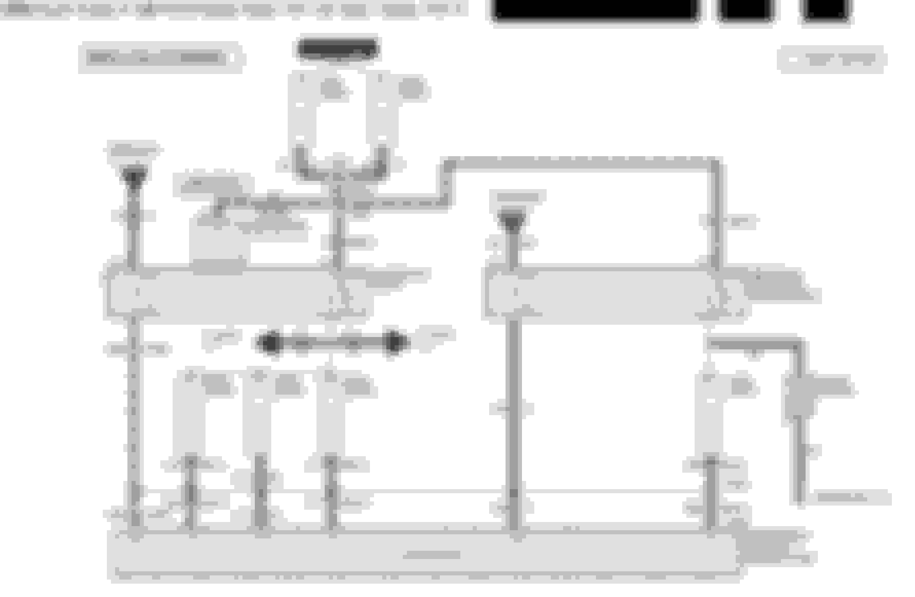
The attached are the circuit diagrams for your Glow Plug System; amazingly, they're very simple really. With a Digital Volt Ohm Meter (DVOM) and a few back-probes (you can use small paper clips straightened out) Just be extremely careful when testing anything PCM related.
If you print them out and use two highlighters and color all the (+) one and the (-) the other you’ll have the entire circuit isolated and it makes it easier to identify.
Use the DVOM to check each portion of the circuit and you will find the issue. And, it will be easily repaired.
I sincerely hope this helps in diagnosing the issue.

 07-09-2015, 08:57 PM