When you click on links to various merchants on this site and make a purchase, this can result in this site earning a commission. Affiliate programs and affiliations include, but are not limited to, the eBay Partner Network.
I was wondering the same thing about your plate. I'll know better when I get mine in the mail, but here is a shot from when 51fordfan did his. It looks like the plate from Bond is designed around the original retainer, so that means I'd need to use the bushing since the 4 speed one won't line up with the T5. Hopefully I get mine in soon and I'll post some photos to clear it up. Thanks Tinman.
I just fabbed the spring base out of scrap (the little loop that the return spring hooks onto), and screwed that into the face of the alu plate adapter from Dwight. The holes were more than a "just don't line up" there were 3 holes in the new trans face, and 4 in the old spaced evenly (so at best I might have gotten 1 to line up, but even at that the spring base was at 3 oclock instead of where it need be at 12).
I didn't want to screw into the trans as drilling, tapping, then *removing any shavings from the trans* would have been a complete disassembly.
Dwight has made changes over the years and so a very old one doesn't look identical to a new - he no longer cuts all the extra material away so it is a little more square then the one you pictured.
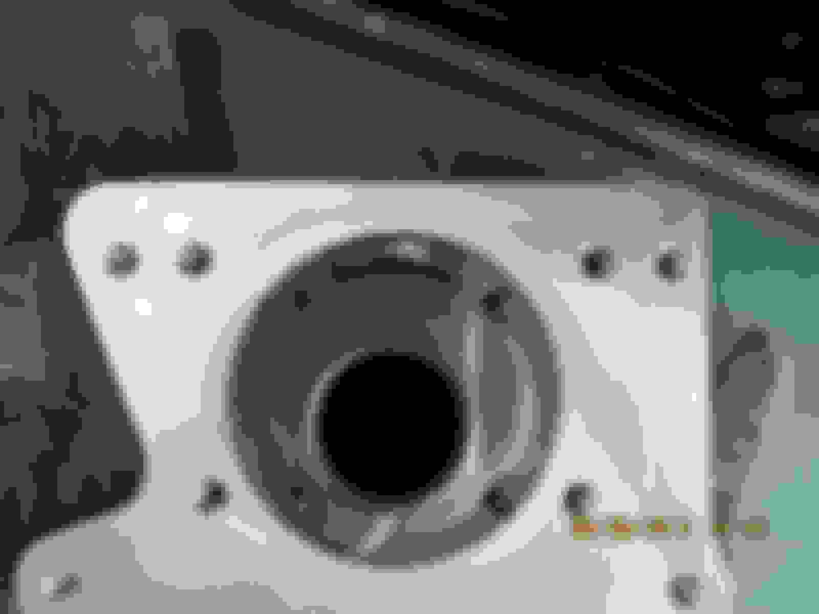
mine is similar and different to tinman's.
I have the same flat side on the left (drivers side).
I have the same recess so it will go over the top of the trans bearing retainer.
I do not have the raised lip.
I do not have the 4 holes for the old bearing retainer.
So in total mine has 11 threaded holes (6 for the hogs head, 4 for the T5, and 1 on the side for use in the model A crowd's clutch arm, unused in our case).
Good info guys, thanks! I'll be sure to take some good shots of mine so we can compare. I ordered my sleeve bushing today in case I need to go that route. Updates coming soon...
Would any of you be so kind as to measure the distance from the floor to the bottom of the trans mount where it meets your fabricated brace? I'm looking to start building mine with a similar design as 51fordfan and would like to know if my estimation of 10" is in the ballpark. I know he has about 3" from the floor to the top of the rear of his trans. I just want to know approx how long my side pieces need to be that will attach to the outside of the frame. Also, if you have any pictures I'm sure many of us would appreciate it. I do not have the rubber piece that goes between the trans and crossbar yet, but will order soon. Thanks!
No can do until Saturday. Don't know if you caught the drama story, but my whole life is in a box and the truck is mothballed. I'm in flux right now on the living situation and don't really have access to my life other than weekends
If ya still need on sat ping me and I'll go check. I made the bottom part of my crossmember removable via several bolts. Several bolts to make it stiff enough to still act as frame, but also removable since that big long trans wont come out through the passenger compartment anymore.
No problem Bryan, sorry to hear about all your troubles bro....... Don't worry about the measurements, you have enough on your plate. A buddy of mine who recently got a welder helped fab up a brace for me tonight. I made the down pieces 8" and that should give me enough room to play with. I used 2" C channel for the bottom and 4" flat for the down pieces. It's just some stuff he had laying around, but it should work out fine (I hope). Here are some shots:
Maybe a hair thin,but we doubled up where the bolt holes will be drilled (not pictured).
Implements of rust destruction for the boys to use tomorrow while I'm at work.
Once the rust is gone I'll knock down the rough and sharp edges and get it painted. I gotta make use of the sun and +30 deg temps!
Some pretty good progress this week here in the Far North. After the boys killed the rust on my trans crossmember I was able to prime and paint it (until the paint ran out). Then I started to get some parts in before the weekend hit:
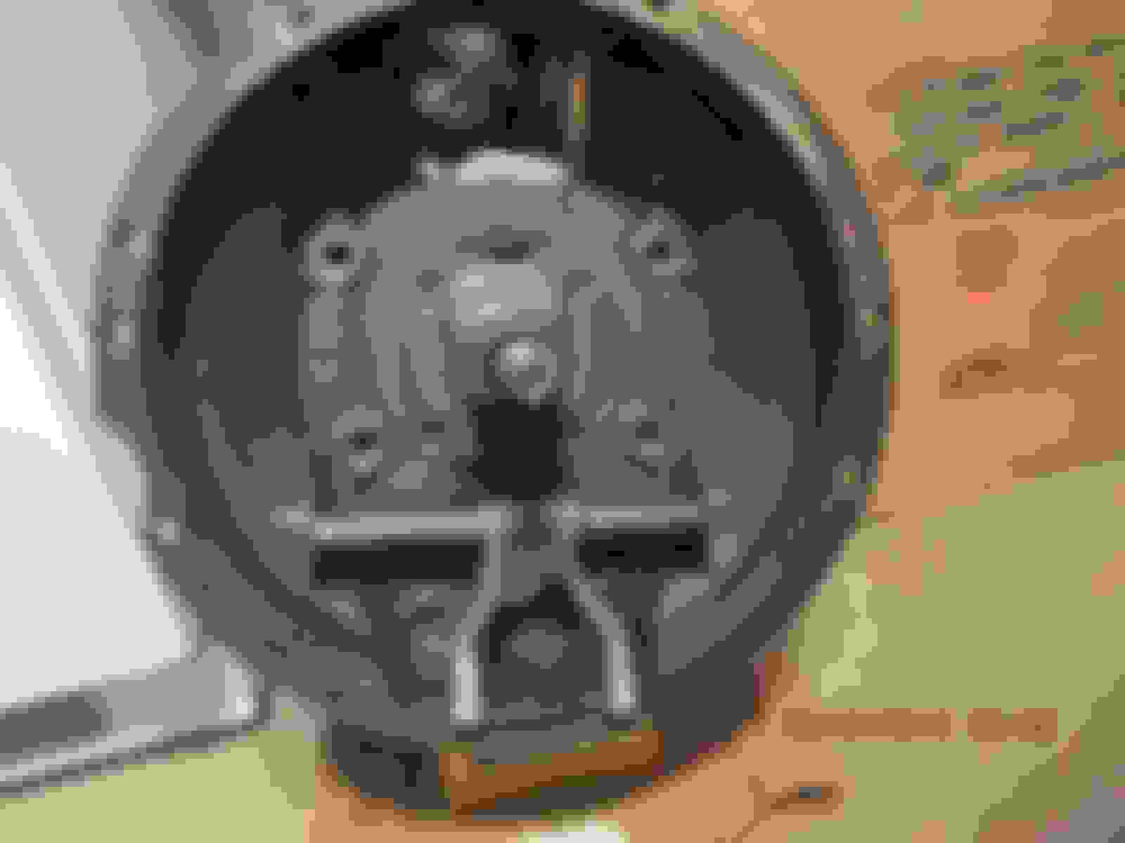
It looks a lot like yours Tinman, but the shape of the bushing threw me off a bit. It that was your guys' looked like? I'm thinking I may have to mill off the smaller section as it will likely hit my clutch disc. Please let me know if I'm wrong.
I started looking at what to do with my shiny new brake line that will be in the way.
I even knew better when I put it there, but thought a T5 was a pipe dream...... So I've just bent it up and out of the way for now.
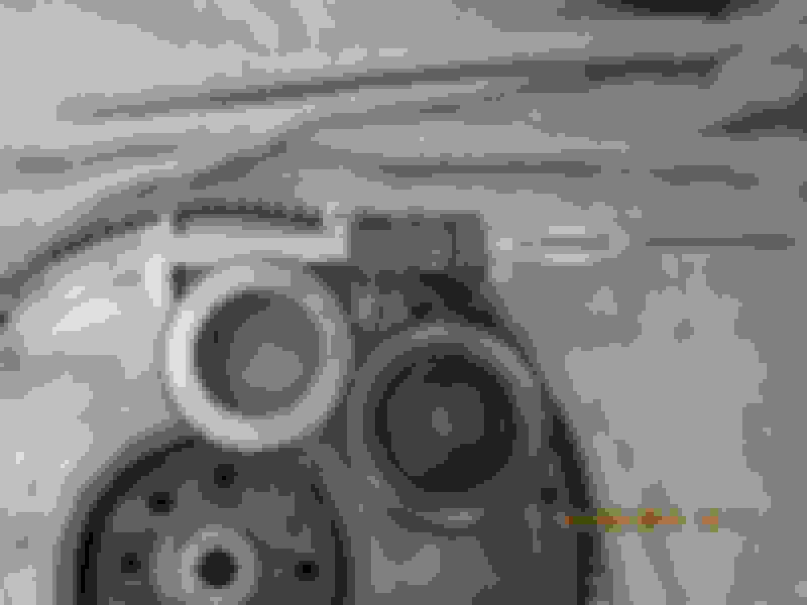
I started to mock things up a bit:
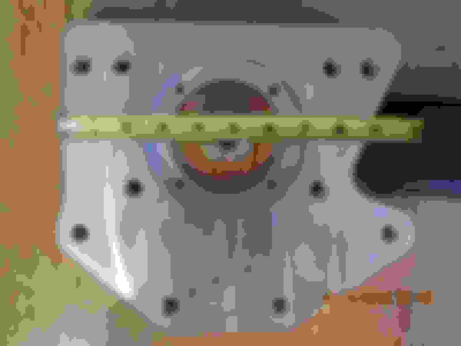
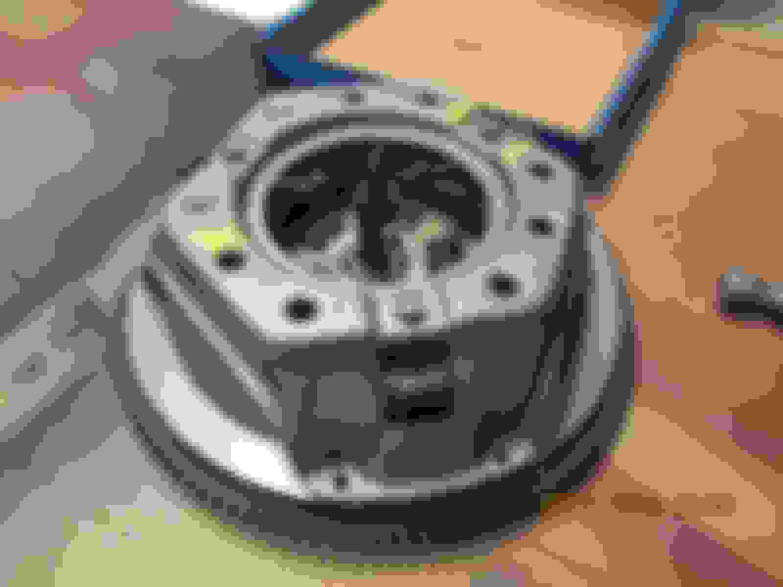
I wanted to see if my 4-speed hub would work or if I would have to use the 3-speed or go with the bushing inside the original assembly to match up with the T5.
Notice how the holes ALMOST line up!
Bummer....
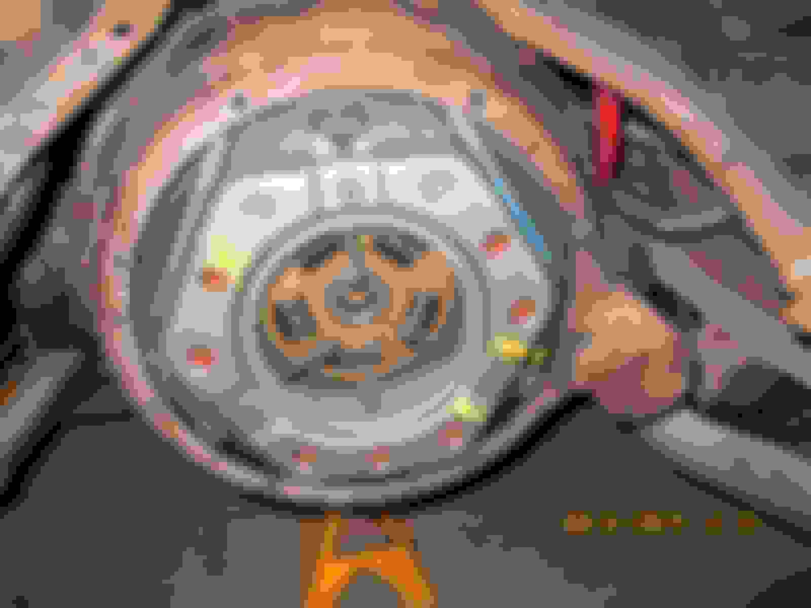
So I thought I'd try to hone the holes and see if I could get them to line up.
I didn't want to risk making the holes any bigger as they are close to the edge already, so I used the side of a drill bit to hone them in the direction I needed.
It worked like a charm (but better):
Then as stated earlier, I had to enlarge the holes in the trans to match the 1/2-13 threads that are in the plate:
I took VERY slow and easy as I did not want to break off the ear.
That'll do it.
I did some more mocking things and checking sizes to be sure it looks right:
This pilot bushing slides over the shaft just fine
My new throwout seems to match the old in all dimensions.
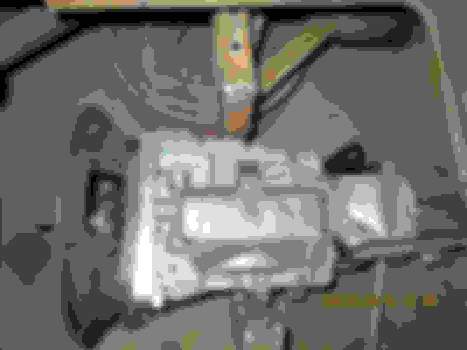
Thought I'd take some pictures of part numbers to share:
I went ahead and cut this guy off too:
I had some trouble with getting a socket on the upper bolts the mount the plate to the trans:
No go on drivers side
A little trimming did the trick
In order to get the socket on the passenger side I had to push the bolt head forward so I could then get the socket between it and the screw behind it.
That made it problematic when tightening down the plate because the plate was about an inch or so from the trans when I stared to tighten things down. I had to be careful to tighten it all evenly so as not to break off one of the eras on the trans from the torque. Kind of hard to explain with the computer and all, but if you've ever had to do it you know what I mean.
I wanted to put the trans mount on but then I realized that one of the holes was very stripped and enlarged, so I went ahead and tapped them both out:
Again, I went slow and methodical so as not to break on ear off.....
I eventually got the mount on and then transcribed the measurements over to my crossmember.
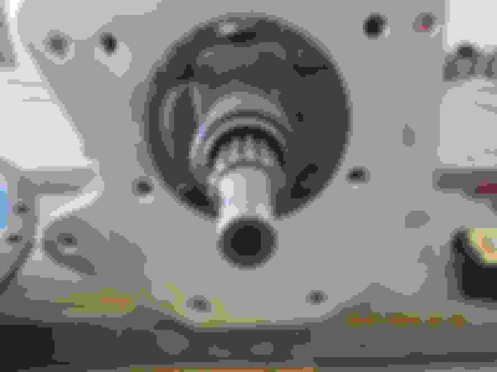
I then measured the distance from the hogshead to the end of the shaft to compare to my earlier measurement:
The original 4-speed was about 2 7/8" and this one is about 3 3/8" however after much measuring I don't believe I will have to trim it. Time will tell.....
I took this one in case someone wants this measurement:
All in all a good week! Next week I'll take the flywheel/disc/pilot bushing/hub/thowout bearing into the machine shop and let them do their magic.
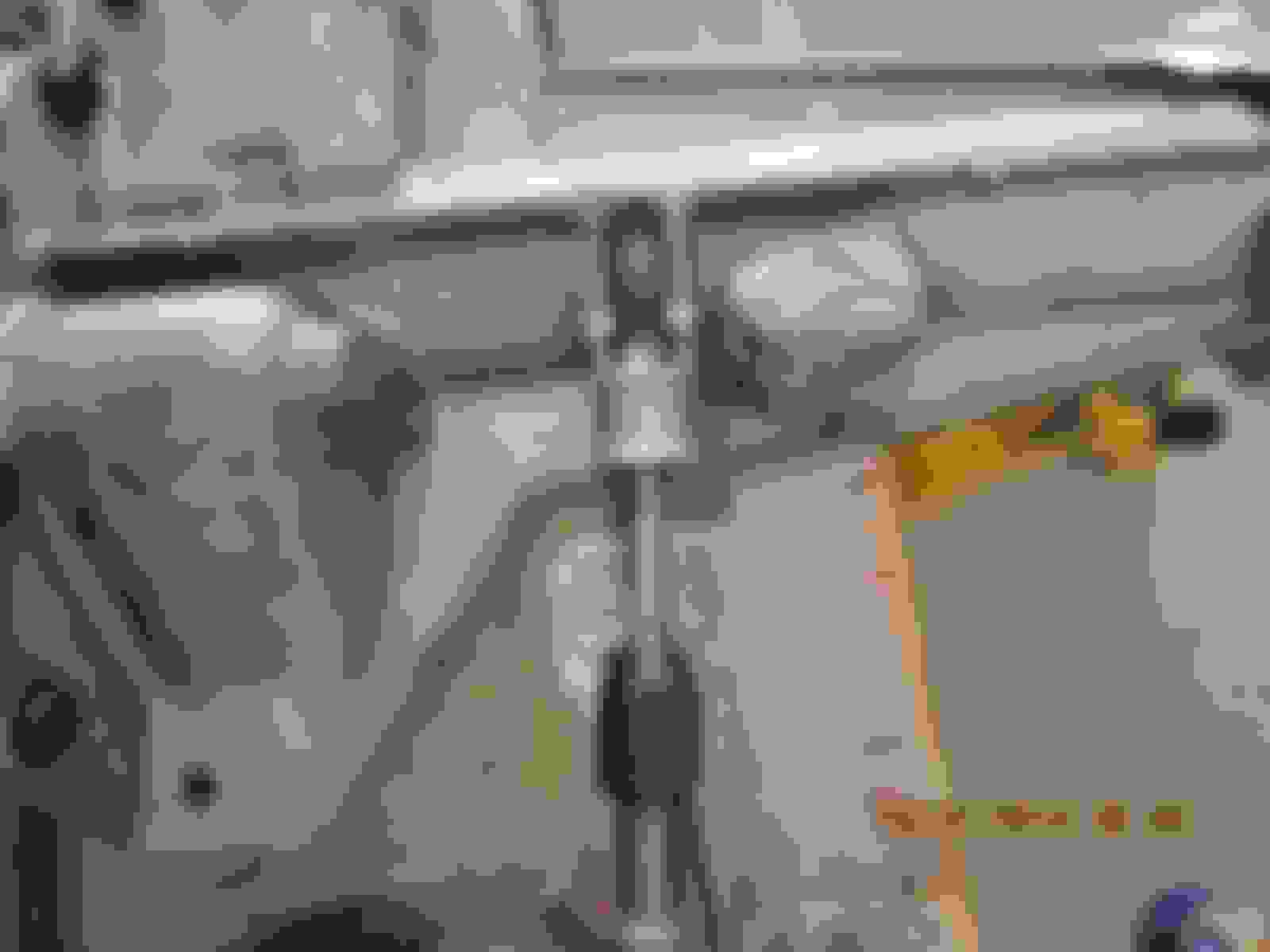
I wanted to ad a couple shots of the painted trans crossmember. It will mount on the outside of the frame and I'll be sure to take plenty on pictures and measurements:
Yesterday my buddy came over with a welder and we got the crossmember ready to except the T5.
My plan was to weld in gusset braces (one on each side of the crossmember) and then cut the center section out.
We started with 3/8x1 1/2" flat bar and bent it with a sledge hammer and a maul used as a anvil. No pictures of that clown show, but here's what they ended up looking like:
This one went from the driver's side of the crossmember to near where the clutch linkage is attached to the frame.
You can see the bottom edge sticking past the bottom of the xmember to the left of the scribed vertical line.
Vice grips holding it in place.
Here you can see the pass side brace going towards the rear.
The scribed vertical lines are where I made my cuts with a sawzall. I took out 10".
More 3/8 on the ends to stiffen things up since I didn't put braces on the top.
Things were tight under there, and my buddy is a bit of a novice so the welds aren't pretty, but they seem plenty solid with good penetration.
I'll go through and cut off the overhanging edges, grind off the sharp corners, and maybe slap some paint of them before I take closer pictures.
Today I picked up my flywheel after having it machined for the clutch disc as well as surfaced. I then dropped it off at another place to have it balanced. I will need to also drop off my pressure plate so he can balance it all together. That will set me back a few days because I won't be getting into town for a bit. I stopped at the driveline shop and bought a yoke that will slip over the T5 but will match the existing ujoints. That way the ujoints will all be the same and easier to find/replace. Once I have the trans mounted I will slip on the yoke and take my measurements for the shortened length. Patience......
Not a lot to report for the T5 install today. I decided to balance the pressure plate with the flywheel, so it will set me back several more days as I haven't got into town to drop off the PP. In the mean time I installed one mirror, polished up some metal, ground down some sharp corners from the xmember welds, and put in the new throwout bearing. I'll post some pictures of the mirror and polish in my build thread, but I do have a couple for this one as well.
Here's the yoke I bought that will slip on the T5 and match the Ford U-joints.
And the throwout bearing:
Greased it up a bit
Fits great.
Last but not least I picked up the clutch alignment tool from Autozone, 4 bucks.
Big day yesterday. I got the flywheel and PP back from getting balanced and started putting it all together. Here's what got done:
All balanced and ready to go!
He marked with paint and 2 dimples to make it easier to find during assembly. That came in handy later on when it was hidden at the bottom and I had to feel for the dimples to line everything up.
Cleaned the face with steel wool and acetone.
Here are the thin head bolts I went with:
Height difference in old and new.
Dry fit:
Start assembly:
Cleaned it one more time before the PP went on. I also cleaned the PP face as well.
PP was torques to 20lbs
Marked this to check depth one more time before putting in the trans. I did not have to cut any off the shaft (so far).
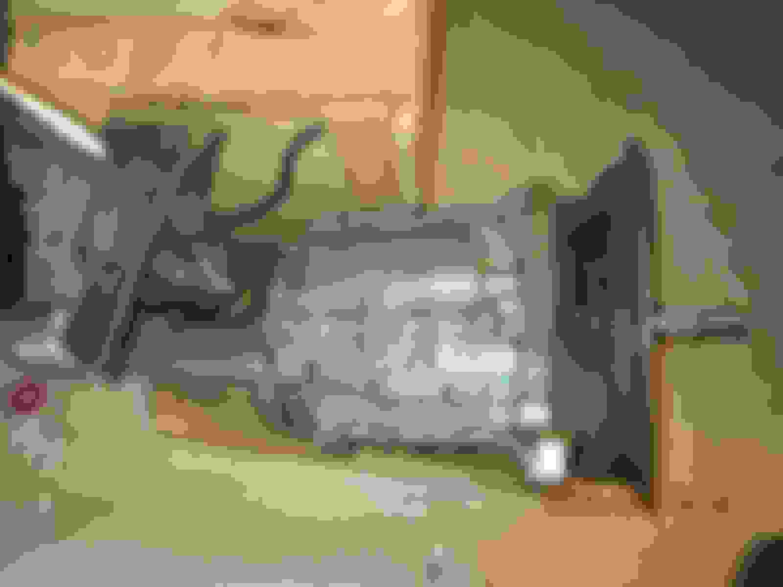
Bell housing on.
Now for the real test. I had let mom and the boys go see a movie, so it was just me putting this pig in.
Tried this first.....
No go because I made the opening in the xmember too small.
I ended up using the same method I did to get it out. Straps around the body and in through the cab.
I started to measure my angles to see if I will need to shim the rear end in order to achieve less than 3deg difference in the trans angle and rear end angle. I'm around 8deg now....
 03-16-2015, 09:41 AM