Help From Electrical Gurus
#1
 03-02-2015, 09:35 AM

Help From Electrical Gurus
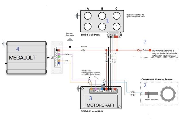
HELP – I am putting together a Ford EDIS (Electronic Distributorless Ignition System) ignition system for an old Flathead engine
The EDIS system is made up of:
• EDIS module, #3
• Megajolt, #4
• crank trigger wheel, #2
• variable reluctor sensor (VRS), #2 and
• one or more coil pack(s) #1
The idea of this system is to generate a signal by using a crank trigger #2 on the front of the engine. The rotation of the crank trigger #2 past the VRS #2 creates the signal and sends it to the EDIS module #3.
The EDIS #3 module runs the signal thru its internal computer #3 and if it is reading the Megajolt #4 it passes the signal to it. – If the signal from the Megajolt is absent the EDIS #3 goes to a “Limp Home” mode that sends a signal to the Coil Pack #1 to fire a 10 degrees before Top Dead Center (TDC) – This will allow the vehicle to get you home or to a garage – If the signal is passed to the Megajolt #4 it will be analyzed and the correct amount of advance and RMP will determine a signal back to the EDIS module – The signal that the EDIS module gets will cause the correct EDIS #3 coil #1 to fire the appropriate spark plugs
NOTE: in this configuration only the signal from the VRS #2 as combuberated by #’ 3 & 4 are used to replace the operation of the standard distributer and coil. More information such as manifold pressure, throttle position, egt, cam position and several others can be sent to the Megajolt #4 after being combined to enhance the timing signal
In the below diagram of the EDIS system you can see the wiring needed for its operation – My help required is the 12V power wiring physical layout – The EDIS module #3 and the Megajolt #4 require power from the same source and need to be grounded to the same spot – It is strongly recommended that the Megajolt #4 be mounted inside the vehicle
Can a Buss Bar be placed after the relay #? And three separate 12V wires be run to each of the components?

#2
03-02-2015, 09:50 AM

Fleet Owner
#3
03-06-2015, 02:13 PM
Ross thanks for the reply
The trigger wheel pick up id located at the right front of the crankshaft pulley - The two wires coming off that run in a shielded bundle and can be affected by electrical interference - That and the hot wire to the EDIS drives me to mount the EDIS mid way along the right front splash shield - I think I will mount the Megajolt next to it and see how it takes to the harsh climate there vs the harsh climate either on the inside or outside of the fire wall - As I sit here typing this I have changed my mind about 10 times and I'm screaming now
The trigger wheel pick up id located at the right front of the crankshaft pulley - The two wires coming off that run in a shielded bundle and can be affected by electrical interference - That and the hot wire to the EDIS drives me to mount the EDIS mid way along the right front splash shield - I think I will mount the Megajolt next to it and see how it takes to the harsh climate there vs the harsh climate either on the inside or outside of the fire wall - As I sit here typing this I have changed my mind about 10 times and I'm screaming now

Thread
Thread Starter
Forum
Replies
Last Post
Tim Hodgson
Electrical Systems/Wiring
32
10-01-2017 09:54 AM
mwilliams0326
1987 - 1996 F150 & Larger F-Series Trucks
9
04-13-2016 06:14 PM
hivoltj
1987 - 1996 F150 & Larger F-Series Trucks
5
04-20-2012 04:43 PM