
Exhaust Heat Control Valve?
#1
 02-12-2015, 08:46 AM

Exhaust Heat Control Valve?
So I've tried reading all I can to understand the vacuum schematics so I can answer questions on my own, along with help from this site and Google I have a fair understanding. My problem is identification of components. I can read acronyms all day but without a visual aid to help sadly I'm clueless. I have multiple hoses plugged or capped, or routed different than they are suppose to be. I have taken pictures of the several culprits in hopes they can show the problems better than I can describe.
First up The Exhaust Heat Control Valve. Currently there is no hose. I understand it runs to the Distributor Vacuum Retard Delay Valve. Where exactly is this VRDV?
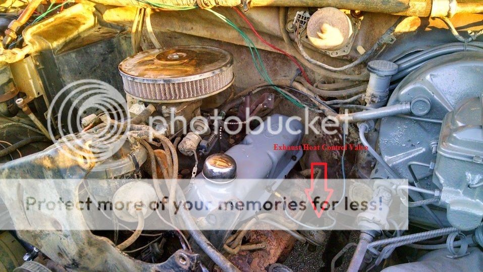
I will make these posts as short as possible and hopefully just ask one question at a time so as not to flood this post with a dozen questions of locations for all these vacuum components. Thank you in advance.
#2
02-13-2015, 11:38 PM

A VRDV is a vacuum delay valve (VDV) that allows vacuum to be built up in one direction, and allows it to slowly bleed down, and will not allow vacuum to be built-up (acts straight-through) in the other direction.
It is a small plastic cylinder, bigger in diameter than it is long, with a plastic nipple sticking out each end for the vacuum hoses to attach to. So it is an inline gizmo. Maybe an inch or so in diameter.
An Exhaust Heat Control Valve - Eeeek! Not one of Ford's better ideas! I luckily never had a vehicle with one on it. They were notorious for rusting up and causing all sorts of driveability problems.
#3
02-14-2015, 08:45 AM
So I think it's safe to assume I do not have one. So do I really need that component? The diagram shows it has a few inputs like a VCV and an ACV and one line going to intake HCV. is there a chance anyone has pictures of these components?
I can read about their function and understand the system but I have no clue what they look like or where they are located on the engine.
I can read about their function and understand the system but I have no clue what they look like or where they are located on the engine.
#4
02-14-2015, 09:09 AM
Postmaster
#5
02-14-2015, 11:47 PM
I'm curious, what is your goal on this obviously hacked-up truck?
I ask this because I assume this truck originally had catalytic converters, air pump, TAB and TAD valves, check valves in series with the air-injection tubes, air tube (like an upside-down T) going to the back of each cylinder head, and an air injection tube to each cat converter, plus EGR system and PCV system and fuel evaporative control system with carbon canister storage and purge... Is any of that on it anymore?
Are you just trying to get the Exhaust Heat Control Valve working properly again? Have you tested the EHCV itself to see if it works, or is the diaphragm shot, or is it all just a rusty hulk on/in the exhaust manifold?
If you just need to get the EHCV working again for cold-weather start-up driveabilty, we can probably piece enough together to do that function, if the EHCV itself is still useable.
I also have to ask... in your pic what is that ball chain doing that looks like it is hooked to the accelerator cable linkage?
Just curious.
I can answer a bunch of emission control questions, that doesn't bother me. I won't say I have all the answers, but I can try. And I'm not bashful about saying "I don't have any idea!"
#6
02-15-2015, 05:05 AM
Postmaster
#7
02-15-2015, 05:10 PM
Well my goal is to have a good running engine and it seems like having a good working vacuum system is a very important role. I know it does not have most if any of the emission systems such as EGR or Cats. I am sure this is the reason for so many capped off or missing lines.
As for the EHCV, it was just a random thread start as I have so many things I could use help with but not sure where to begin. Does the EHCV play a role in the proper running of the engine. Currently I am only getting about 9.5 MPG and aside from a full tune up I feel this vacuum system disaster might be a reason for poor economy.
I do still have the PCV running from the Pass. side valve cover to the back of the carb. I to have the fuel canister, now as to if it is fully operational I am not sure.
I have several other pictures around the engine of vacuum components that have missing lines or plugged lines and everyone here is my best chance at figuring out what is needed, what is not, and how to get it back to a workable condition.
Trending Topics
#8
02-15-2015, 05:13 PM
#9
02-15-2015, 11:24 PM
So vacuum leaks are a real possibility... you could try disconnecting and plugging all vacuum, except for the PCV, Power Brake Booster, and the distributor vacuum advance feed. This will separate out all the other stuff from the engine basics. See if there is any difference then. With no vac into the cabin, the heater/vent will default to the defrost outlets at the windshield only, that is to be expected.
Exhaust Heat Control Valve - I would look into whether the shaft that moves the valve is stuck, or what. The basic principle is that when the engine is cold, the valve is closed, which effectively prevents cylinders 5 - 8 from putting exhaust out the manifold exit on that side. Instead, exhaust from the those 4 goes up through the intake manifold's exhaust crossover passage, heating up the intake manifold runners near the carb, and then that diverted exhaust exits via the passenger side exhaust manifold, along with exhaust from cylinders 1 - 4 on the passenger side.
When the engine coolant warms up, a VCV was to switch off vacuum to the HCV and vent the vac motor, allowing the valve to open and exhaust to flow normally.
At least with the earlier design HCV idea, which was controlled by a bimetallic strip at the valve instead of vacuum, if a person got on the accelerator harder when the valve was closed, the backpressure would open the valve up some, so you could GO! And then easing up on the gas, the valve would close down again if still cold.
IF the HCV is stuck in the "closed" position, then those poor 4 driver-side cylinders have one heck of a load to fight against all the time, like having a partially restricted exhaust. That would not be good for gas mileage
Oh, and it gets worse... I looked at your photobucket pics, and saw a pic of a well-weathered vac diagram, I assume that is your truck's. And a nice drawing from a book. BOTH have, in addition to the Exhaust HVC, an INTAKE HCV (INT HCV). Lucky you. That is ANOTHER vacuum-controlled valve, that resides in the well in the intake manifold that is in the exhaust crossover passage.
On the intake manifold, passenger side, near/back from the carb base. That well used to be used for carb choke air-heating, to help the bimetallic choke spring to open the choke plate sooner, it used clean air from the air cleaner, through a steel tubing coil sitting down in the exhaust flow, and then into the choke. Air was pulled in via an orifice in the choke housing, to provide the suction to move the air. THAT method was used on many cars of the 60's - 70's.
But you have an electric choke-assist heater (the wire to the choke). And the well is being used for another vac-controlled heat valve. I am not sure WHY they needed TWO valves! I'll guess, this is only a guess: The HCV on the exhaust manifold, when open, allows xhaust to flow on to the exhaust pipe. However, the path to the intake manifold crossover is still open, so some gases can still go that way. Maybe that valve up in the intake well would block the flow, like it was Closed, when the exhaust manifold's valve was Open, and the intake manifold's valve was Open (to allow crossover flow) when the exhaust manifold's valve was closed (to provide backpressure to get exhaust to flow up there).
I had a 1982 302 Country Squire wagon, and a 1983 302 L. Mark VI, neither had any sort of HCV, they both had exhaust crossover passages that were open all the time. The 1982 Ford had a Variable Venturi carb, and 52 miles of vacuum tubing in layers upon layers with plastic gizmos all over, including a rack of sealed adjusted vacuum sensing switches. The 1983 Mark VI, in contrast, was CFI injected, had very little vac hose, and much much better throttle response. I much preferred to work on the '83!
Both passed the required emission tests with flying colors.
#10
02-16-2015, 01:21 AM
well you saw several pictures than I have not yet put into threads to hopefully resolve my vacuum trouble woes. Yes the colored picture of a faded vacuum diagram is mine under the hood, and the black and white one is from Chilton's online for an 84 5.0 with manual trans
So maybe first thing is finding out if this Exhaust HCV is malfunctioning into the closed position, and if so what do I do? How and/or can it be removed or forced into a fixed open position?
You threw a bunch of amazing information at me and I am incredible surprised that such a complex vacuum system (at least to me) would be used on something from the mid-early 80's.
It seems I really need some help in trouble shooting as I have little experience for carb run engines.
I have owned plenty of Fords in my day but of the 8 only 2 have been carb, 1 my current bronco with factory carb and such, the other being a 73 F-100 with a 360 and Edelbrock carb and only the basic 3 vacuum components mentioned earlier (PCV, Brake, Dist.)
Should I go an post my other pictures of various vacuum lines plugged, cut or missing so you all have an idea of just what I'm looking at or should I start a different thread?
#11
02-16-2015, 11:32 PM
Does this look like your Exhaust Heat Control Valve?
www.rockauto.com/info/4/105011_1.jpg
I found that at rockauto, under Exhaust>Heat Riser. I hate it that they called it a "heat riser", as that always caused confusion, people confuse it with an intake air preheater, the metal tube that would bring heated air up to the snorkle of a temperature-controlled air cleaner housing.
Anyway, that and both types of left exhaust manifolds, with and without HCV are also on rockauto.
I would try to get the shaft free, if it is stuck closed. Penetrating oil of your choice, left overnight. It's also possible its all rusted up permanently, and if closed, it will have to come off, and butterfly removed, and if the casting is still OK, like will still seal to manifold and exhaust pipe, not eroded away, put it back on. It's also possible that once apart, the HCV and/or the manifold may be toast, and may have to get a HCV or come up with a housing, or get a new exhaust manifold (w/o HCV then).
If it were me, I'd really try to free it up first, if no go, then I'd take the HCV off and try to make it free-flow. Dealing with manifold-to-cylinder head bolts/studs can be a bit of an ordeal if one or more twist off. If one or more snap off, it's better if they snap off farther out, and not flush with the cylinder head! So I'd start with the easier pieces first, and see if that will do it.
I assume the manifold that did NOT use an HCV is longer than a HCV-equipped manifold, to make up the same length, but that is my assumption, not fact.
Even though that will make this thread very long, at least all the info will be here all in one place. Separate posts per part or pic may lead to questions about the basics, what are you trying to accomplish, etc. etc. and you may have to repeat and repeat. That's my slant, anyway. If you really want to do them separate, go ahead, just have to repeat the initial conditions over and over.
www.rockauto.com/info/4/105011_1.jpg
I found that at rockauto, under Exhaust>Heat Riser. I hate it that they called it a "heat riser", as that always caused confusion, people confuse it with an intake air preheater, the metal tube that would bring heated air up to the snorkle of a temperature-controlled air cleaner housing.
Anyway, that and both types of left exhaust manifolds, with and without HCV are also on rockauto.
I would try to get the shaft free, if it is stuck closed. Penetrating oil of your choice, left overnight. It's also possible its all rusted up permanently, and if closed, it will have to come off, and butterfly removed, and if the casting is still OK, like will still seal to manifold and exhaust pipe, not eroded away, put it back on. It's also possible that once apart, the HCV and/or the manifold may be toast, and may have to get a HCV or come up with a housing, or get a new exhaust manifold (w/o HCV then).
If it were me, I'd really try to free it up first, if no go, then I'd take the HCV off and try to make it free-flow. Dealing with manifold-to-cylinder head bolts/studs can be a bit of an ordeal if one or more twist off. If one or more snap off, it's better if they snap off farther out, and not flush with the cylinder head! So I'd start with the easier pieces first, and see if that will do it.
I assume the manifold that did NOT use an HCV is longer than a HCV-equipped manifold, to make up the same length, but that is my assumption, not fact.
Should I go an post my other pictures of various vacuum lines plugged, cut or missing so you all have an idea of just what I'm looking at or should I start a different thread?
#12
02-18-2015, 07:39 AM
Ok well aside from the Exhaust HCV I have what I feel is a mess of a vacuum system. Here are some pictures with what I am working with. First up is a couple diagrams of my vacuum system

Taken from Chiltons

Taken from under the hood

As you can see above there is nothing going to these, plus they are not plugged.
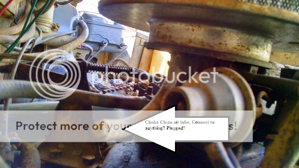
This Clean air choke tube is plugged, should it be?

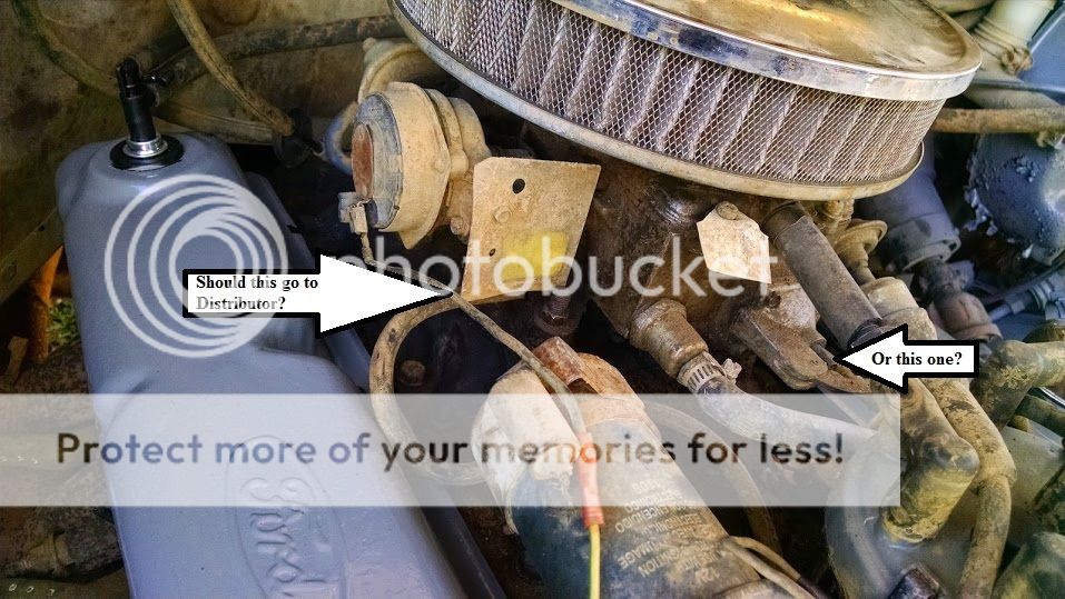
Recently plugged the big line coming from the front center of carb as I was told if its not going to a valve cover breather it can be plugged. My Vacuum diagram shows the distributor getting its line fron the Driver side "CARB T" while the line I currently have going to the DIST. is coming from "CARB C" which is suppose to go to the TVS, V REST, VRDV, and AIR BPV. Where are all these other components???

Are these two small lines part of the heat/ac vent system?

These 3 go into this Intake vacuum but what are they for and what are these 3 suppose to be hooked up to?

Another plugged line coming off this vacuum port located on the intake manifold behind the carb same as brake booster
Those are all I have. This hole vacuum thing seems to be taking me in circles. I appreciate all of your help in figuring this situation out.
#13
02-18-2015, 07:41 AM
#14
02-18-2015, 11:16 AM
#15
02-18-2015, 11:48 PM
I am able to move the Heater valve by hand but now my question is if the default position is closed or open? I would think open, but if it is used to aid in warming the engine, would it not require the engine to reach operating temperature through the vacuum system to fully open it?
The VCV sits in a coolant passage to sense coolant temperature. Internally, the VCV has a temperature-sensing wax pellet, like a thermostat has. When the coolant gets warm enough, the wax melts and expands, pushing a piston upwards, that moves the VCV's valve parts on top to cause the switch to change position. All connections to a VCV are all exposed (i.e., there is no internal vac path from inside the manifold or anything like that).
When the coolant temp goes down enough (in this case, engine off and cooled), the wax solidifies and contracts, and internal spring pushing down on the piston/valve assembly causes the valve to change states again.