When you click on links to various merchants on this site and make a purchase, this can result in this site earning a commission. Affiliate programs and affiliations include, but are not limited to, the eBay Partner Network.
Your doing a great job Ax. If everyone else is like me, they are watching and learning, but don't want to clutter up the tutorial with a lot of chatter. Thanks and please continue, it is very appreciated.
Lower rear of fender at running board and doubler (area in blue on drawing)
This area of the outer fender skin and the doubler had significant rust damage. A previous repair was attempted by sliding a thin metal patch between the remnants of the doubler and the outer skin. This patch piece was not welded but was held in place with the running board attachment bolts. An undersized patch has been brazed to the outer skin. A layer of bondo was added over the outside before the fender was primed. Because of the poor condition of the metal, the repair attempt, and the importance of this area to the integrity of the entire front clip and the stress stepping on the running board would produce on it, we decided to replace the entire lower 5 inches as well as fab and install a new doubler.
Here you see the previously repaired section that was cut away and the newly formed replacement section already tacked in place above it. Note the braze and the extra �tripler� (rusty piece held by thumb): Removed damaged section compared to new patch already tacked in place.
A cut line was carefully measured 5� from the fender bottom. A flexible straightedge was used to make sure the line was straight. As with the previous patches, a piece of posterboard was attached with magnets and the area was carefully traced before being cut away with a cutoff disk. The cut edge was trued with a flat file. It was noted that the edge of the area was rolled into a �J� shape along the curved section and transitioned into a flat squared bend flange along the straight portions. We would duplicate this in the new patch. To form this compound flange we would form the patch flat first using a modified MDF hammer form and then curve it by shrinking the flat portion of the flange with the shrinker.
To aid in making the curve the right shape a 1/8� hardboard horizontal template of the curve was created along a line 3� from the bottom, parallel to the cut line.
The first posterboard pattern was retraced onto another posterboard and a 3/4� flange was added to the three sides. (3/4� was slightly narrower than the original flange but is the max depth of the shrinking machine.) A 2� wide strip was added along the cut edge so the hammerform screws would go through this area to hold the metal in place in the form. That pattern was traced onto a new piece of sheet metal and cut out. The first pattern without the flanges was traced onto 2 pieces of MDF that were temporarily screwed together in the waste portion. (the yellow colored part in the drawing 3-1
Forming the patch: This patch was more complex looking than the previous ones, but it was easily made with basic tools in several steps to be covered in detail. The only major tools used were 140A Mig welder with .025 ESAB Easy Grind wire and Ar-CO2 shielding gas, Shrinker/stretcher set (I use Mittler Bros) not necessary can be worked around, but very useful and inexpensive enough to be affordable investment for anyone seriously wanting to do body work. Drawing 3-1
Unlike the previous patches this needed both a square bend and a J rolled edge, so a modified hammerform was made to form these two types of bends. Two pieces of 3/4� MDF were screwed together and cut out to the pattern on the bandsaw. The screws were removed and the face piece of the form was marked and trimmed 1/4� where the J bend was to be produced (red line in drawing). After trimming the two pieces were realigned and the cut out portion traced onto the back piece as a guide line. A compass was set at 1/4� and used to draw another guide line along the edge of the piece, then a small palm sander was used to create a quarter round along the edge where the J bend was needed. See the cross sectional drawing, the yellow color represents the back piece and the red color the trimmed front piece.
Using a wooden punch and hammer, the flange was slowly bent over the form. Bend the curved portion slowly using 6 - 8 passes trying to avoid making flutes in the metal as it compresses. Some minor fluting may be inevitable, but try to roll the first part of the J as smooth as possible, as per the �first bend� in the next drawing. We will finish rolling the J over a curved rod later. The square bend portions of the flanges were bent over the hammerform as for the previous patches. Drawing 3-2
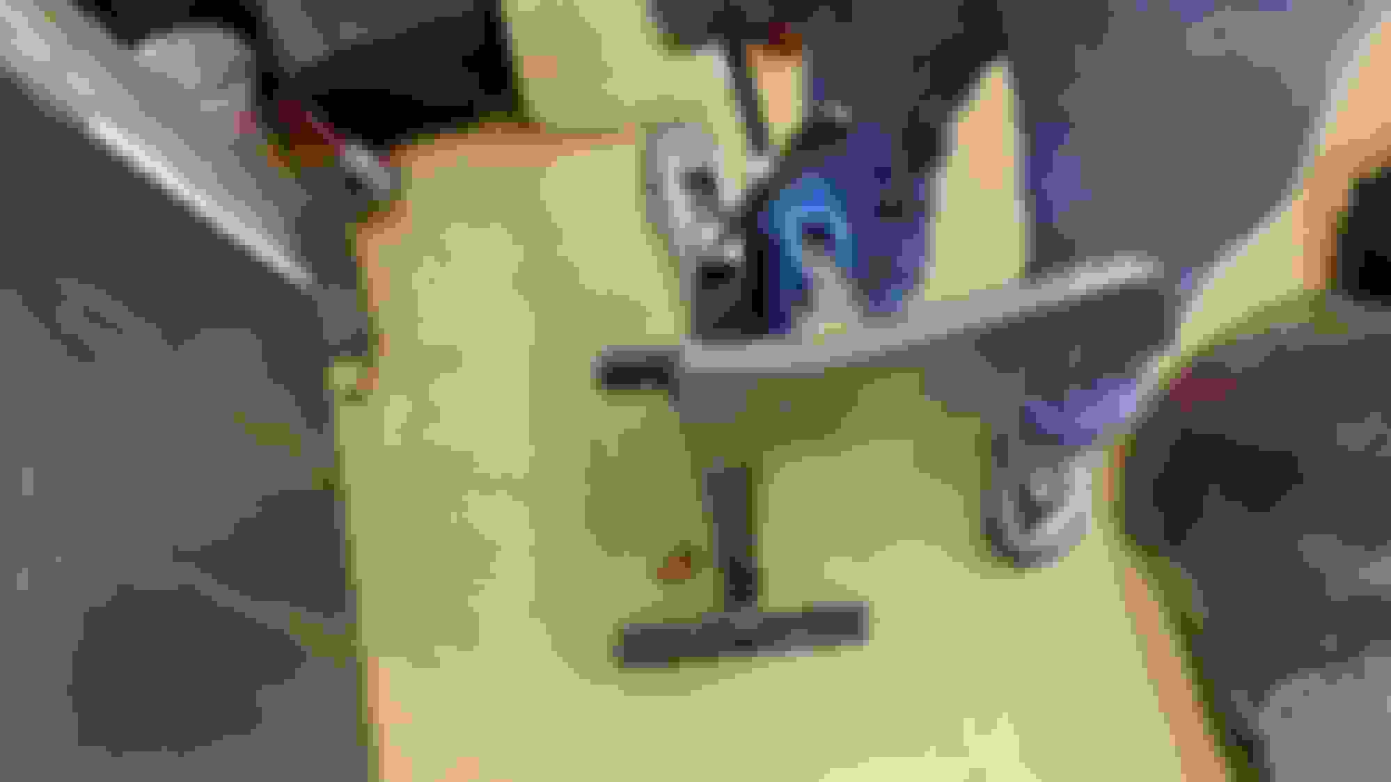
Next step was to form the flat patch into a curve using the shrinker. Keeping the hardboard curve pattern at hand the square bent portion of the flange was run through the shrinker, moving the flange � a jaw width each stroke of the handle. Comparing the flat patch to the template of the curve desired
Ready to shrink flange to curve patch
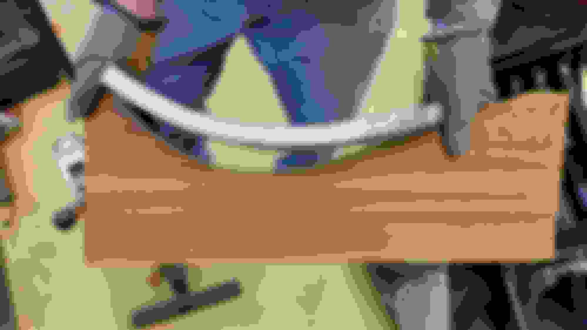
First pass through the shrinker
Each subsequent pass will cause the panel to curve more dramatically since you are reshrinking metal that has already been shrunk.
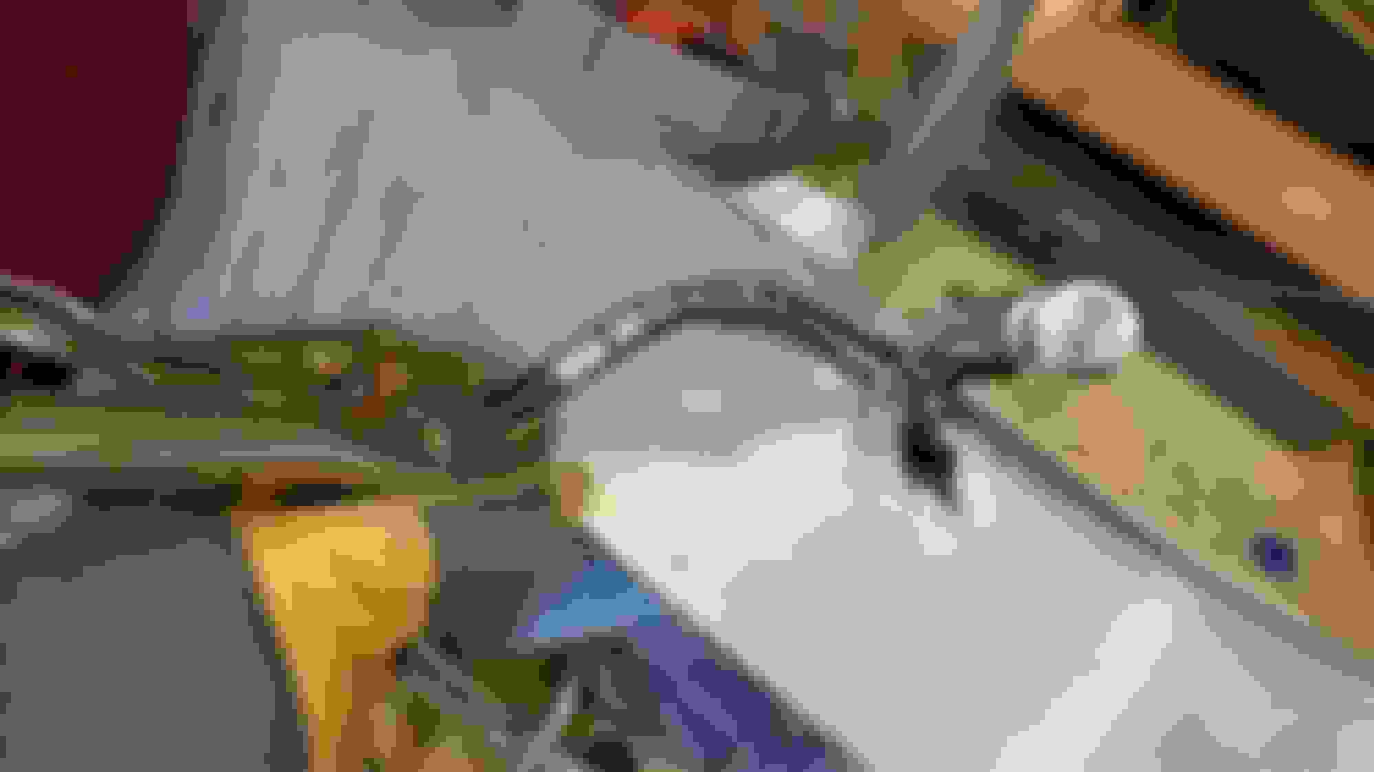
Comparing pattern after first pass
Patch curve matches pattern
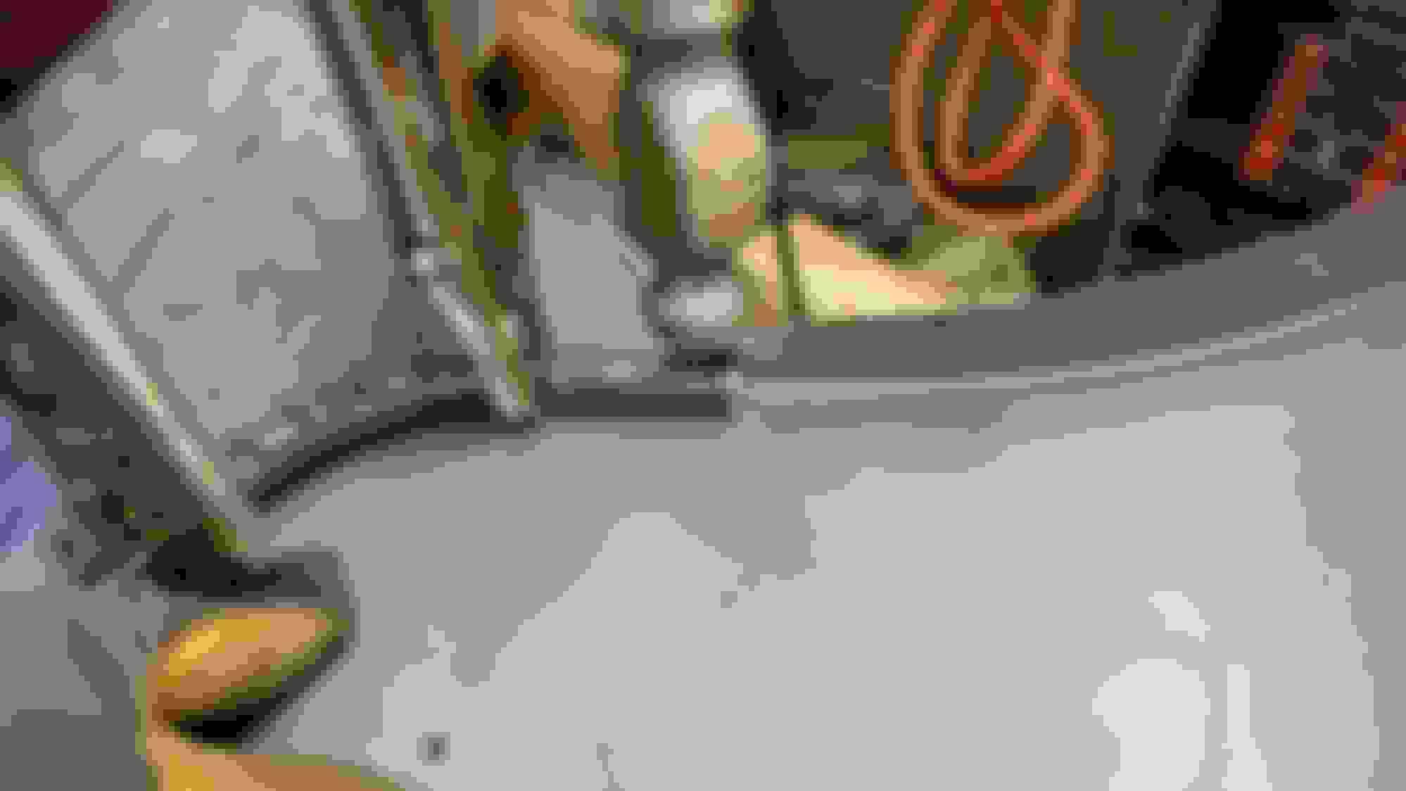
After 3 passes and small adjustment. Note marks on flange indicating where the adjustment was made.
It's important to use even pressure on handle and move the piece evenly in small increments through the machine to keep the curve smooth. Should the curve get too tight, the stretchercan be lightly used to adjust it back out. Take your time to get it right.
The patch was cut along the cut line to remove the waste portion and draw filed with a 12� flat file to straighten and true the cut. When it was test fitted and the ends aligned, I noticed the center of the cut did not meet. Checking I realized that portion of the fender also had a shallow compound curve top to bottom. To make the cut edges match and put in the shallow compound curve in the patch I ran the cut edge lightly through the shrinker. The next test fit was perfect so it was time to tack the patch in place. To align the J bend in the fender and the patch and prepare to finish rolling the J into the patch a length of 1/2� (to allow for spring back to needed 5/8� inside roll) steel rod was heated with a torch and bent to match the shape of the rolled edge of the patch. It was cut long enough to extend past the seam, and clamped in place. A thin cutoff wheel was used to cut a series of narrow V's into the still unbent portion of the J bend, and the tabs were gently hammered around the mandrel to complete the J. The cuts will be welded closed after the patch is tacked in place.
Bending the tabs to complete the J shape.
Note the last tab under the vise grip still needs to be bent.
Ball end of ballpeen used to form transition between J and straight flange.
Patch seam perfectly aligned and ready to tack weld
A small piece of angle iron was used to align the cowl end of the patch flange to the fender.
Patch tacked in place.
Note the tight fit of the seam and alignment of the edges to create a continuous flow. A kink in the edge at the seam would be a dead give away that it was repaired.
Next the slits in the inside of the J were welded closed. To reduce the possibility of burn through, a 1� strip of 20 ga copper sheet was formed into a ring around the steel mandrel. The copper ring was slid along the mandrel under the slit to be welded and the mandrel clamped in place to act as a heat sink. The copper prevents accidentally welding the mandrel into the fender permanently.
Welding the slits closed. Copper band around mandrel.
Tacks being added along seam.
The seam was finish welded by adding a series of tacks about 4-6� apart, and allowing each series to fully air cool before adding another series.
Seam fully welded (face side)
Note how narrow the heat affected zone is along seam yet the seam has full penetration as shown on back.
Full penetration weld (series of overlapping tacks) back side.
Note: slits in J roll also fully welded same way, mandrel removed. This took about 4 hours in total with cooling time in cool shop. Ready to be ground smooth and metal finished.
Outside weld ground down ready for metal finishing.
A 40 grit red fiber sanding disk on a 4� angle grinder was used, pausing frequently to allow the metal to cool so as to not cause warping. Care was taken to not thin the metal along the sides of the seam. There are minor low spots from heat shrinkage (dark areas along seam) that will be picked smooth.
Inside seam and J roll needing one more grinding pass to smooth.
16 ga Doubler
A new doubler for inside lower fender to replace one completely rusted away. The doubler reinforces the running board mounting, was made from 16 ga hot rolled sheet in two pieces, a flat piece bent into a curve and a C shaped flange welded together.. The doubler will be plug welded in place inside fender after the fender is metal finished.
Next installment will cover the metal finishing methods used. Goal is to make all the metal smooth enough to need no more than 1/16� skim coat of filler to be ready for primer.
Axracer,
once more you've come up with the goods! Another VERY informative post on how to do things right! I will be referring to these instalments when I start on my F1.....(when the temperature in my garage gets above zero!)
Thanks again.
Last edited by tiger100; 02-17-2015 at 07:10 AM.
Reason: spelling
Very Very nice AXracer!! this will help and motivate a lot of us on here! I too am waiting for the garage to get to at least 25 degrees before I kick on the heaters...
excellent work. Since most of the front and rear F1 fenders I have seen are rusted along the running board mounts and anywhere else where there was a factory doubler, you would think somebody would make patch panels for them, but this is a great alternative if you have the patience to follow these directions carefully and not get in a hurry. thanks.
Thank you ax
You used 16 ga for the backer? Was the patch 18 ga? And if so why
We are using the same ga metal as Ford used originally wherever possible. The patches are made from 19 ga deep drawing (also called aluminum killed) cold rolled steel, really nice stuff to work with. Doublers are made from 16 ga hot rolled (what I had on hand in my shop). The black oxide was sanded off the hot rolled before welding.
The really important stuff (metal finishing) is coming up.
excellent work. Since most of the front and rear F1 fenders I have seen are rusted along the running board mounts and anywhere else where there was a factory doubler, you would think somebody would make patch panels for them, but this is a great alternative if you have the patience to follow these directions carefully and not get in a hurry. thanks.
Patience is the key! My father used to say "There is never enough time to do it right the first time, but always time to do it over" I'll be emphasizing patience a lot in the metal finishing coming up.
Ford didn't believe in priming or painting the back sides or between any metal. I'd guess his philosophy was "they are only work vehicles and are going to get f****up anyways." and it didn't make good business sense back then to make a vehicle that would last 10 years much less 50!
Fortunately our trucks have fairly simple lines, so patch panels are not that difficult to fabricate. I have found that there is significant variations in the factory panels even side to side, so the likelyhood is that mass produced patch panels would/do require a lot of massaging and rework to fit anyways. FWIU they used to make patch panels but there just wasn't enough demand.
 02-13-2015, 11:38 PM