When you click on links to various merchants on this site and make a purchase, this can result in this site earning a commission. Affiliate programs and affiliations include, but are not limited to, the eBay Partner Network.
I didn't know Ididit changed their column design. My Ididit column has a solid 3/4" round shaft with the end ground to a DD in it, not the 1" hollow tube swedged to DD as in the pictures here. I have no idea when they changed or if all their columns now use the hollow shaft. My column is their paintable plain steel jacket tilt column, floor shift, dash mounted ignition switch model.
I also missed where you said you were using an LTD front clip, which has a horizontal swing pitman arm box, cross steering setup. I don't have any answer for you for that setup, Sorry for the bad info.
Thanks everyone for your input.
I called Borgeson today and they suggested moving the steering box. I shimmed it about .250 and it looks like to will line up. I just need a couple of u-joints and a short shaft. They said that small amount of shimming can be adjusted out when it is aligned.
I did find some good info on cutting an Ididit column. This applies to solid inner shaft, not the hollow one like I have. I'm not sure where it came from or I would give credit to the author. I thought I should post it here in case anyone else may need it:
Shortening an Ididit column:
1. Mark the cut line on the outer housing by wrapping a strip of poster board about 2 1/2" wide and long enough to go around the housing about 2X. Line up the edge of the PB with the length mark and make sure the PB is wrapped tight and the overlapped edge exactly lines up. Trace the edge of the PB with a fine line sharpie to give a straight and square cut line. Cut along the line with a cutoff wheel or hacksaw. (If you use a hacksaw DON'T saw all the way thru like a baloney, saw until the blade just breaks thru. rotate the housing and continue the cut until the blade breaks thru again. Repeat until the housing is cut all the way around. DO NOT nick the steering shaft in the center of the column!) I used a cut off wheel. Slide the cutoff off the inner shaft, debur the housing.and set the column aside for a few minutes. NOTE: another way to mark a square and straight line around a tube is to use an appropriate sized worm drive hose clamp. Slide the clamp onto the tube, align the edge of the clamp with the cut mark, and tighten the clamp tight. Mark along the edge of the clamp.
2. Examine the cutoff and note the HMW plastic bushing in the end that centers the lower end of the shaft. Look carefully around the outside and you will see two very small holes. The holes are actually the center of two small roll pins that lock the bushing into the housing. There will be two slightly larger holes inside the bushing that line up with the outer holes. Use a small diameter pin punch or similar tool slightly smaller than the roll pin diameter (I actually used an appropriate size allen wrench, 1/16" if I remember correctly) and tap the pins in just far enough to clear the housing thickness and slide the bushing out of the cutoff, noting the small flange on one end.
3. Remove the pins from the bushing by pushing them out from the inside of the bushing. I used the same allen wrench hooking the short leg into the hole and prying on the wrench. (The pins will slide out fairly easily. so if it doesn't you are doing something wrong) Push the pin out just enough to grab it with a pair of pliers and pull out completely. Repeat with other pin. Set the bushing and pins aside (DON'T lose the pins!)
4. Here's the critical part: Continue the flats on the inside shaft that make it the DD shape by using a straight edge and scribe to continue the lines of the 4 edges up the shaft the length of the shortening, 2" in my case. Carefully grind in the continuation of the flats and dress them flat and smooth to the lines with a file. (the shaft is just mild steel, so it is easily reshaped) NOTE!: DO NOT leave a square shoulder where the flats end and the shaft becomes round, or use the grinder or file or any cutting tool like a hacksaw, crosswise to the shaft to end the flats to give a crack a place to start. I used a 1/4" grinding wheel in my 4" angle grinder to grind off the excess metal running the wheel parallel to the length of the shaft so the diameter of the wheel left a natural radius at the end of the flat. I used a small drum sander to smooth this radius, making sure that even the finest scratches were all parallel with the shaft length. Finally I sawed off the excess shaft and chamfered the edges of the shaft end to make it burr free and make sure it didn't hang up in the U joint when steering.
5. Use a drill the same size as the original pin holes in the outer housing and drill two new pin holes in the outer housing and about 1/2 way thru the bushing. Don't bother trying to hit the old holes in the bushing. Rotate the original holes in the bushing about 90* to the new hole locations, push in the bushing until the flange sits tight to the housing and mark a small witness mark on the bushing and housing with the sharpie before drilling the new holes. Don't insert the pins yet! Remove the bushing and continue drilling the new holes until they break thru to the center in case you ever want to disassemble the column again. Now replace the bushing and tap in the roll pins until they are flush with the outside of the housing. Admire your now shorter column and install it in your truck!
Yes, I did get it finished up. I used a u-joint with a vibration damper. It is just a little shorter than the 2 u-joints and short shaft. So the steering column didn't need to be cut.
I was trying to use a built-up floor plate using the original split plate and the 2 u-joints with a short shaft. I made the plate and tested it but as you can see in an earlier post that would require the steering column to be cut down. Since the steering column shaft was hollow and I would have had to send it back to Ididit to be shortened. This would have worked but I didn't want to send the column back.
So I abandoned that idea and made a whole new one piece plate.
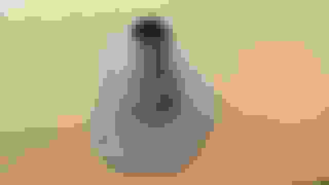
U-joint with the vibration damper and shimmed steering box. Lined up great.
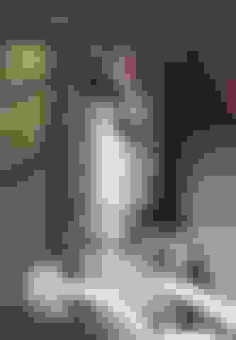
Column painted and installed. Much better than it was!
 12-07-2014, 10:25 AM