Bye Bye Front Drums
#121
 11-19-2014, 09:23 PM

While I was replacing my '69 F-100's manual fixed steering column with the '78 PS tilt column, I didn't have the tilt column steering coupling (rag joint) to connect it to the Saginaw power steering gear box.
I pressed the old splined flange off the end of my '69 manual steering column shaft and drove it onto the splines of the tilt column shaft but, it didn't have the bolt going through it for the column end, like the tilt column coupling would have had. It did couple up but, I just don't feel good about it not being the right part for this application.
It seems the '78/'79 tilt column coupling/rag joint is made of unobtainium and virtually impossible to find.
I knew that Borgeson makes high quality steering U-joints (I have one that's designed to couple a Ford 3/4"-36 spline column shaft to a 2003 Crown Victoria Vee steering rack intermediate input shaft and it's a very solidly built piece).
After searching the net, I found some Borgeson components that may solve the problem in the lack of available Ford rag joint couplers for this application.
The first one is a rag joint coupler Borgeson makes.
Borgeson 053434, Borgeson Rubber Coupling/Rag Joints | Borgeson
Another possibility is a full on U-joint style (available in aluminum, steel or stainless steel).
Borgeson 113434, Borgeson Steering U-Joints | Borgeson
The second (U-joint) style will transmit more vibration into the steering wheel but, I don't know that I'm too concerned about that. --this is an old truck, where the NVH is already pretty 'crude' by today's vehicle standards.
There is a vibration reducing Borgeson joint that's available. I'm just not sure if it would be too long to fit between the steering box and the steering shaft (?).
Borgeson Universal Company :: Vibration Reducers :: Steel Vibration Reducer U-Joint
Anyway, these MAY be some possible components to use if you're installing a tilt column in your Bumpside truck.
#122
11-22-2014, 06:07 PM
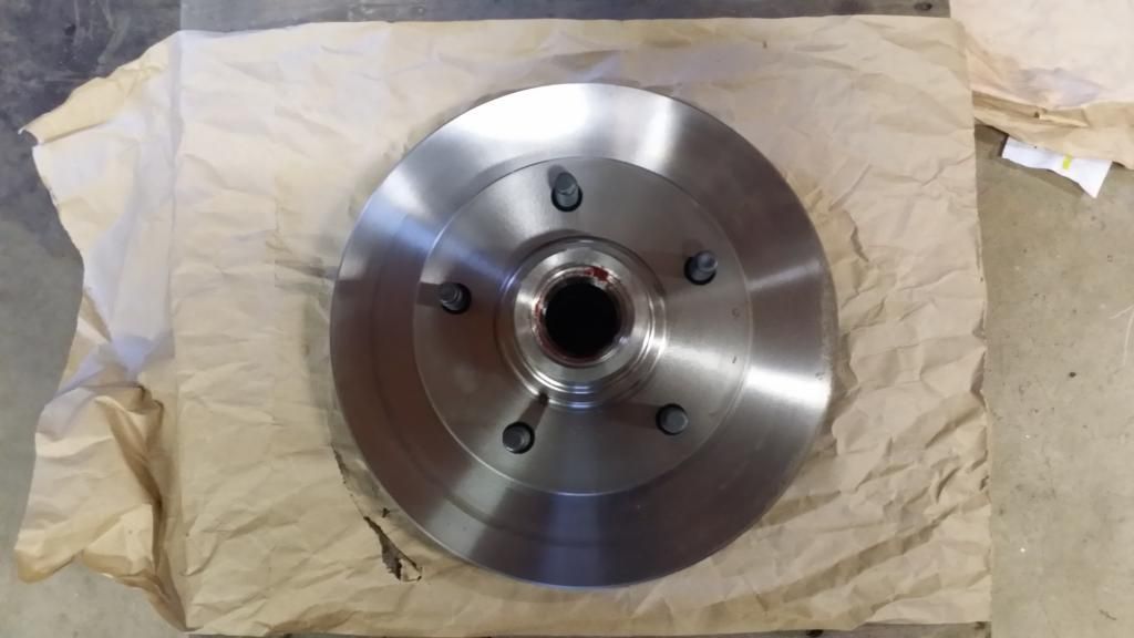
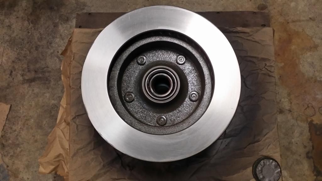
During the time I've been making changes on my truck, we've had a good bit of rain here. The moisture in the air had started surface rusting my pretty new rotors.
Left uncoated, the rust will just continue to spread and get thicker and the rotors will just get uglier --and I can't have that.
The rotor on the right front had a lot more surface rusting than the rotor on the left side.
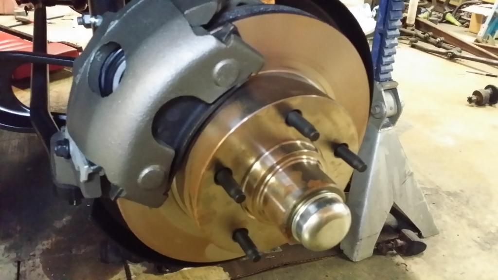
I pulled the rotors so I could mask them off to be primed and painted. Since paint will ruin a set of brake pads, the friction surfaces can't be painted. However, trying to mask a round object with masking tape doesn't really give the best looking results plus, it takes a LOT of small strips of tape to go around something like a brake rotor. Masking tape also doesn't give a nice continuous curve. It's more like a series of small straight lines connected together to somewhat form a curve.
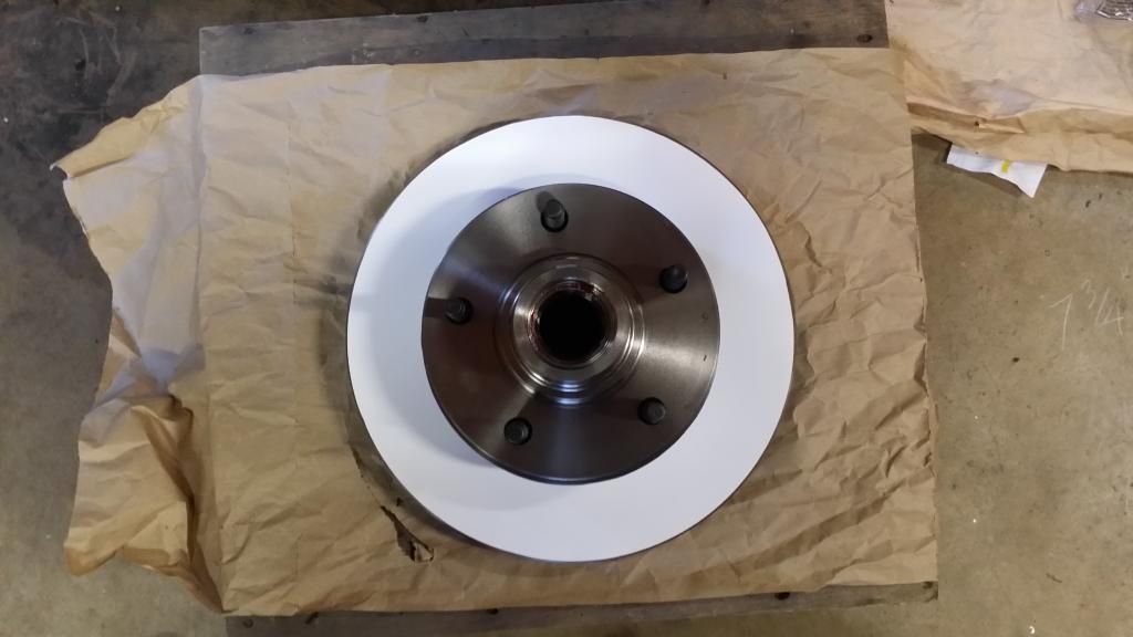
I had some thin Teflon-like sheeting I had gotten from Walmart a good while back (can't remember now what I used it for) but, I thought if I could cut a mask out of it, to lay over the friction surfaces of the rotor, I would be able to paint every surface without getting any (or little) over spray on the friction surfaces and, there wouldn't be any series of short straight lines at the masks edges. It would leave nice, unbroken edges where the paint was applied.
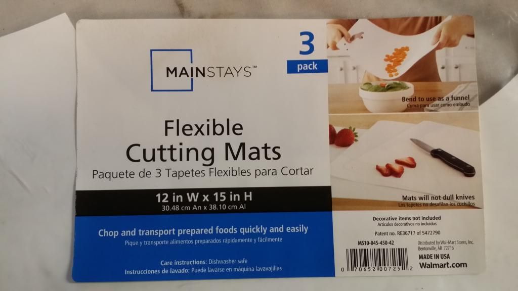
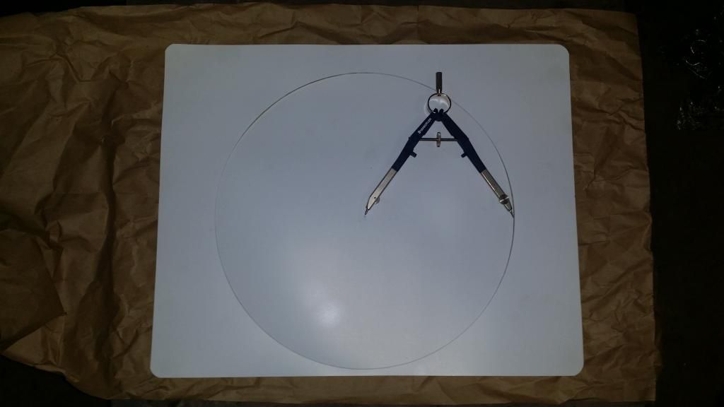
I measured the rotor and adjusted the compass to the needed diameter. The compass has a sharp point on each of the legs. I just drug it around in a circle on the white plastic sheeting until it cut through it.
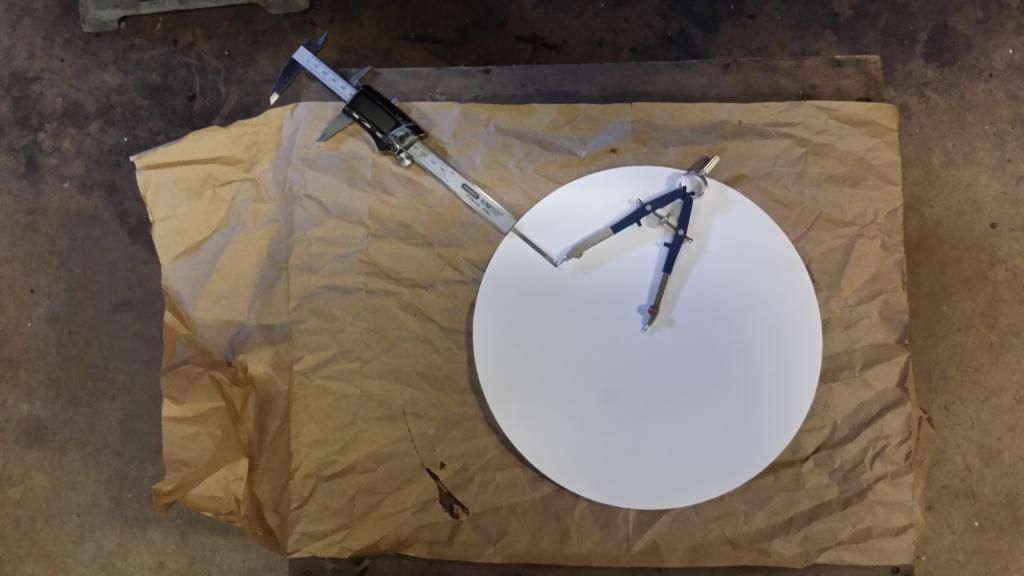
With the outer circle cut, I measured the width of the friction surface to cut out the inner circle of the mask.
The mask cut out and placed over the rotor.
...Looks like a white wall rotor
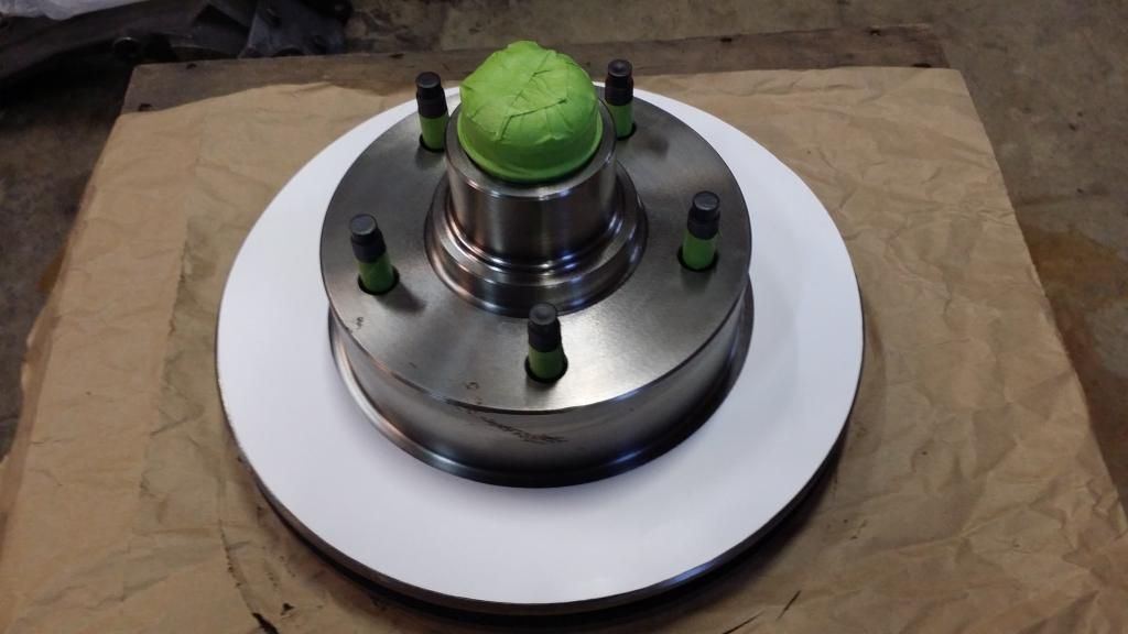
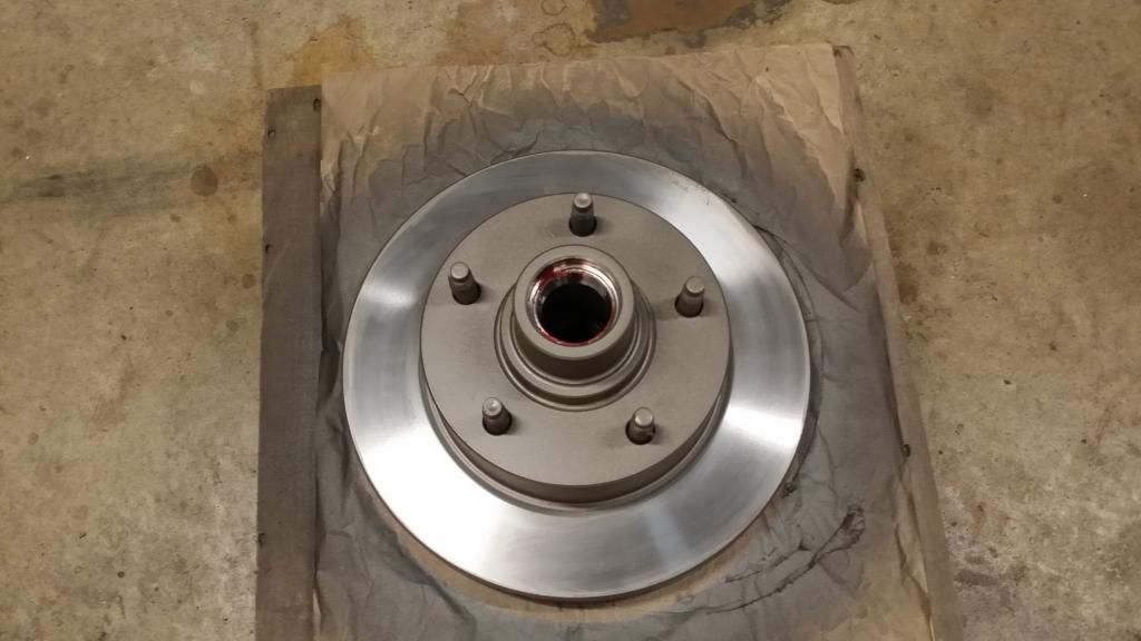
I used the mask on the front and back of the rotor to prime and paint all the surfaces --including the vaned edge, and got only very minor over spray underneath the mask, which was easy to wipe off with a little brake cleaner sprayed on a shop rag. I painted the rotors with Dupli-Color (500-degree ceramic) Cast Coat Iron p/n DE1651.
Left uncoated, the rust will just continue to spread and get thicker and the rotors will just get uglier --and I can't have that.
The rotor on the right front had a lot more surface rusting than the rotor on the left side.

I pulled the rotors so I could mask them off to be primed and painted. Since paint will ruin a set of brake pads, the friction surfaces can't be painted. However, trying to mask a round object with masking tape doesn't really give the best looking results plus, it takes a LOT of small strips of tape to go around something like a brake rotor. Masking tape also doesn't give a nice continuous curve. It's more like a series of small straight lines connected together to somewhat form a curve.
I had some thin Teflon-like sheeting I had gotten from Walmart a good while back (can't remember now what I used it for) but, I thought if I could cut a mask out of it, to lay over the friction surfaces of the rotor, I would be able to paint every surface without getting any (or little) over spray on the friction surfaces and, there wouldn't be any series of short straight lines at the masks edges. It would leave nice, unbroken edges where the paint was applied.

I measured the rotor and adjusted the compass to the needed diameter. The compass has a sharp point on each of the legs. I just drug it around in a circle on the white plastic sheeting until it cut through it.

With the outer circle cut, I measured the width of the friction surface to cut out the inner circle of the mask.

The mask cut out and placed over the rotor.

...Looks like a white wall rotor


I used the mask on the front and back of the rotor to prime and paint all the surfaces --including the vaned edge, and got only very minor over spray underneath the mask, which was easy to wipe off with a little brake cleaner sprayed on a shop rag. I painted the rotors with Dupli-Color (500-degree ceramic) Cast Coat Iron p/n DE1651.


#123
11-23-2014, 12:25 PM
Cargo Master
Join Date: Nov 2005
Location: La Ribera, Baja, Mexico
Posts: 2,694
Likes: 0
Received 43 Likes
on
25 Posts
NICE TRICK AMIGO, AND EVEN NICER RESULTS... BRAVO, AND ANOTHER FEATHER IN YOUR CAP. YOU MUST LOVE TEACHING YOUR COMPADRES NEW TRICKS FOR THEIR SHOP TOOL BAGS. I too have struggled with the tape thing, and have never liked the results... Several packages of those flexible cutting boards are now on my "Bringo" list, to acquire before crossing the border and heading South for the winter...
Thanks again
Baja
Thanks again
Baja
#124
11-23-2014, 06:06 PM
QUOTE=bajafishnut;14844615]NICE TRICK AMIGO, AND EVEN NICER RESULTS... BRAVO, AND ANOTHER FEATHER IN YOUR CAP. YOU MUST LOVE TEACHING YOUR COMPADRES NEW TRICKS FOR THEIR SHOP TOOL BAGS. I too have struggled with the tape thing, and have never liked the results... Several packages of those flexible cutting boards are now on my "Bringo" list, to acquire before crossing the border and heading South for the winter...
Thanks again
Baja[/QUOTE]
Thanks, Baja.
I'm glad if this idea is something you might be able to use too. Once you get the mask cut out, it only takes a few seconds to lay it over the rotor and you can get on with priming and painting.
Taping is time consuming, doesn't leave a clean edge and unlike the tape method, the plastic mask can be reused over and over.
This is the compass I used to cut the mask out with. I bought it years ago. Seems like I also got it at Walmart.
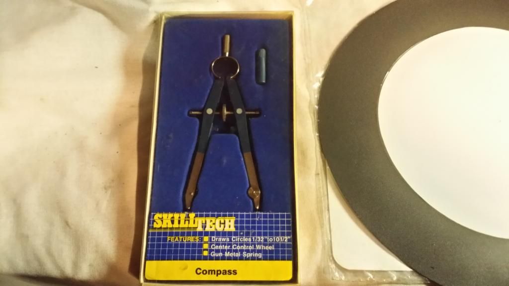
I made the mask a little over-sized on the inner diameter and a little under-sized on the outer diameter. The disc brake pad doesn't make contact with the entire friction surface of the rotor. There's a little gap on the inboard and outboard portions of the disc the pad doesn't touch.
If you make the mask tight to the base of the rotor hat and extend all the way out to the very edge of the rotor, you'll eventually have a rust ring in both of these areas.
I'm dealing with a '77 F-100 front rotor. I adjusted the compass I have a little beyond its intended range capability to be able to cut the outer portion of the plastic sheet. I set the span of the compass at 5-13/16".
The setting on the compass to cut out the inner portion was set at 3-5/8".
I know the F-250 and F-350 disc brake rotors are larger in diameter than the F-100. It's probably not possible to use a compass like this to cut a mask out of the plastic for an F-250/350 rotor--since as I said, I was pushing this compass a little beyond its intended range to make the outer cut for this F-100 rotor.
If your truck is an F-250/350, you will probably have to come up with another means to cut the mask out or, find a bigger compass with a larger range to work with.
Another possibility would be if you have access to a gasket cutter that's capable of cutting out large diameters in materials.
https://www.google.com/search?ie=UTF...07%3B362%3B239
#125
11-24-2014, 01:38 PM
Cargo Master
Join Date: Nov 2005
Location: La Ribera, Baja, Mexico
Posts: 2,694
Likes: 0
Received 43 Likes
on
25 Posts
Still a good idea, and definitely in the class of "Shop Tricks".. While I have opted to keep my front drums, I will paint them before installing, to keep the rust to a minimum. I think that I can just spray them, while face down, without the masking, like a disc brake rotor. Had I not found the drums at Rock Auto, for under $50 ea. I was seriously contemplating spending the money for a disc brake conversion... No need now, thanks to Rock Auto... Now to haul them 1000 miles South, and see if they really do fit, like advertised. The anticipation, will keep me awake on the drive..
What color do you think for my drums... a turquoise like the truck, or Ford blue??
Baja
What color do you think for my drums... a turquoise like the truck, or Ford blue??
Baja
#126
11-24-2014, 02:11 PM
Still a good idea, and definitely in the class of "Shop Tricks".. While I have opted to keep my front drums, I will paint them before installing, to keep the rust to a minimum. I think that I can just spray them, while face down, without the masking, like a disc brake rotor. Had I not found the drums at Rock Auto, for under $50 ea. I was seriously contemplating spending the money for a disc brake conversion... No need now, thanks to Rock Auto... Now to haul them 1000 miles South, and see if they really do fit, like advertised. The anticipation, will keep me awake on the drive..
What color do you think for my drums... a turquoise like the truck, or Ford blue??
Baja
What color do you think for my drums... a turquoise like the truck, or Ford blue??
Baja
Painting the drums the color of the body has the same effect as having the front side of the radiator core support painted the same color as the body (unless the body itself is black) --your attention is drawn through the grille and onto the core support and the focus is not on the grille itself. The grille should be the focal point in the front that gets noticed, since core supports aren't very interesting items to look at. It shouldn't be something that takes away from the grille.
If the drums are a color other than black, your attention is going to be drawn through the wheels and to the drums, instead of noticing the wheels. Drum brakes, like radiator core supports, aren't very impressive items to look at.
But, this is just my opinion and this is my reasoning for it.
#127
11-24-2014, 06:13 PM
Hotshot
#129
12-02-2014, 12:21 PM
Personally, for me, I would not paint the drums any other color than black (Ford semi-gloss black Dupli-Color DE1635).
Painting the drums the color of the body has the same effect as having the front side of the radiator core support painted the same color as the body (unless the body itself is black) --your attention is drawn through the grille and onto the core support and the focus is not on the grille itself. The grille should be the focal point in the front that gets noticed, since core supports aren't very interesting items to look at. It shouldn't be something that takes away from the grille.
If the drums are a color other than black, your attention is going to be drawn through the wheels and to the drums, instead of noticing the wheels. Drum brakes, like radiator core supports, aren't very impressive items to look at.
But, this is just my opinion and this is my reasoning for it.
The guy knew something didn't look right with the front of his truck. It was pointed out the core support wasn't black and it was taking away from the grille.
Before and after. You can see how much difference it makes in your attention being drawn to the core support vs. noticing the grille. --the same would be true of brake drums painted some color other than black.


#130
12-02-2014, 12:40 PM
Post Fiend
^^^ concur. It's like painting brake boosters blue and red poly bushings. Some don't understand contrast, composition, and focal points.
Another is painting grill inserts all black.... sometimes it appears as if parts are missing.
Btw, OCD took over me last winter and applied POR 15 to the rotor's cooling vanes... a little loss in cooling but visible corrosion will be held at bay...painted them with cotton swabs.
Another is painting grill inserts all black.... sometimes it appears as if parts are missing.
Btw, OCD took over me last winter and applied POR 15 to the rotor's cooling vanes... a little loss in cooling but visible corrosion will be held at bay...painted them with cotton swabs.
#131
12-05-2014, 05:46 PM
I had mentioned earlier in this thread that I didn't have the specific rag joint coupling for a tilt column, when I swapped the tilt column into my truck. The tilt column rag joint appears to be nearly impossible to find.
I had a new rag joint, for a non-tilt column, and I had pressed the flange off my old fixed column to couple the tilt column shaft to the Saginaw steering gear box input shaft.
The old flange didn't have as much engagement on the splines of the tilt steering shaft as I would like so, I searched for an alternative.
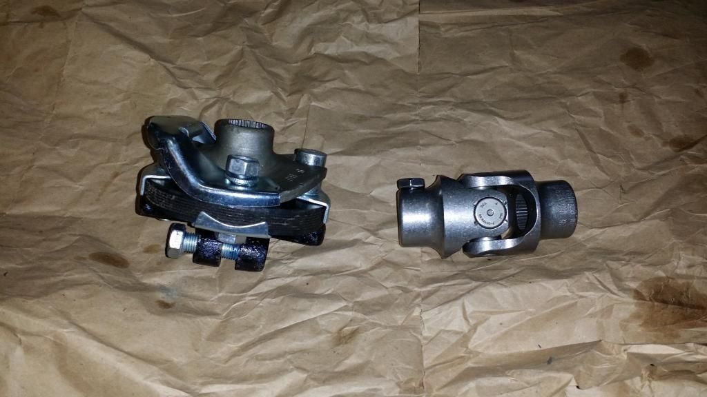
I had also mentioned earlier in the thread about possibly using a Borgeson steering joint instead. I ordered a stainless steel 3/4"-36 x 3/4"-36 Borgeson steering U-joint (p/n SS16N-736X736 113434). I got it from JEGS --$87.97, no sales tax and free shipping.
It arrived yesterday and I got it installed this evening. I feel much better about this component than what I had.
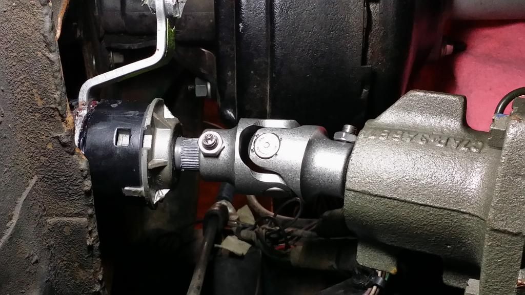
The 'hybrid' rag joint on the left. The new S.S. Borgeson joint on the right.
The Borgeson joint installed. --the upper end of the column wasn't bolted up to the bottom of the dash, when I took this photo. That's why there's an angle to the U-joint.
I had a new rag joint, for a non-tilt column, and I had pressed the flange off my old fixed column to couple the tilt column shaft to the Saginaw steering gear box input shaft.
The old flange didn't have as much engagement on the splines of the tilt steering shaft as I would like so, I searched for an alternative.
I had also mentioned earlier in the thread about possibly using a Borgeson steering joint instead. I ordered a stainless steel 3/4"-36 x 3/4"-36 Borgeson steering U-joint (p/n SS16N-736X736 113434). I got it from JEGS --$87.97, no sales tax and free shipping.
It arrived yesterday and I got it installed this evening. I feel much better about this component than what I had.
The 'hybrid' rag joint on the left. The new S.S. Borgeson joint on the right.

The Borgeson joint installed. --the upper end of the column wasn't bolted up to the bottom of the dash, when I took this photo. That's why there's an angle to the U-joint.

#132
12-06-2014, 11:12 AM
I, have manual steering and my oem mid shaft was getting sloppy u-joint, the coupler rubber dust boot was in need of repair.
So, I bought the Borgeson mid shaft to replace my warn out one on my 4wd.
I thought to myself gees the Borgeson joint has only one set screw to hold it in place since it was a slight angle, I tighten it as tight as I could with out over doing it an doing any thread damage.
I never trusted it an checked it about every 6 months or so. Guess about 2 yrs went by from checking the looseness of the set screw. Wow just as I figured the set screw had play in it. I tightened it up and started thing that coupler really need two set screws on each end to hold it firm.
So I was kind of worried that if, I never checked this over time it would slowly wear the spline on the steering box & steering Column lower shaft.
So found parts to rebuild my ford mid shaft then removed & sold it.
When removing the Borgeson shaft I found the set screw on the joint had eaten into both ends of my steering box & column shaft indented area..
I see where Borgeson has used 2 setscrews on some of their u-joints.
Orich
#133
12-20-2014, 07:18 PM
Cargo Master
Join Date: Nov 2005
Location: La Ribera, Baja, Mexico
Posts: 2,694
Likes: 0
Received 43 Likes
on
25 Posts
Been off line for a bit, due to travel, unloading the truck, install solar panels for the house, and plenty of catch up stuff at the casa... glad that progress is being made on Ultra's truck... btw, the drums will be black, and to Bobby, I finally got my fender flairs put on... photos to follow... flairs and drums...
Baja
Baja
#134
12-20-2014, 10:02 PM
Installing the '78 Tilt Column without Butchering the '69 Main Wiring
Progress has been a little slow lately but, any progress is still progress, none the less.
Over the past week, I've been looking at wiring schematics for a '69 F100 and a '78/'79 F150, in order to decipher what wire ties to what, from the new wires of the '78 column to the old wires on the main under dash harness of the '69.
The wire color codes of the '69 wasn't a problem to sort out but, none of the wiring color codes for the '78/'79 were a 100% match between the new tilt column turn signal switch and the donor main wiring harness connector/pigtail I got from a '79 truck (without tilt/cruise). --this is what took some time to figure out, by reason of deduction, in spite of some wiring color codes being way off from the schematics.
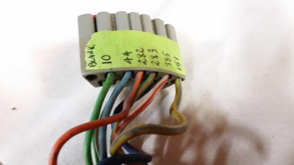
The connector of the tilt column had a large, single, gray connector that all the column turn signal wires were contained in. The '69 column harness had two separate connectors at the ends that tied into two connectors under the dash.
Gray connector/pigtail from main dash wiring harness side of the '79 donor truck.
I didn't want to cut and butt splice (butcher) ANY of the original dash wiring harness of my '69 so, after looking at the situation, the apparent solution was to make a short patch cable to go in between the single column connector and the two original connectors under the dash.
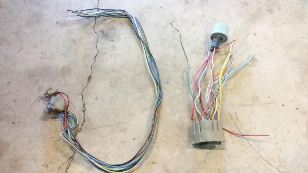
Since I no longer needed the old turn signal switch from the '69 fixed column, the logical solution was to cut the wires on it, to be able to reuse the original pair of connectors and splice them into the '79 main wiring harness pigtail/connector from the donor truck. This would allow me to 'patch' in between the column connector and the original '69 Main dash wiring harness connectors, without chopping up the original main harness.
On the left, my turn signal wires/connectors I clipped off my old '69 turn signal switch. '79 connector/pigtail on the right, I cut from the main wiring harness of the wrecking yard '79 donor truck.
I laid the two sets of connectors out (cut wire end to cut wire end) and began splicing the wires together. When I butt splice wires, for use on a vehicle, I cut the plastic covering off. The plastic insulative covering just adds bulk and if you have multiple wires to connect, a lot of butt splices with the plastic insulation on them will just be a big knot in the bundle of wires, where the splices are. (doesn't look very professional).
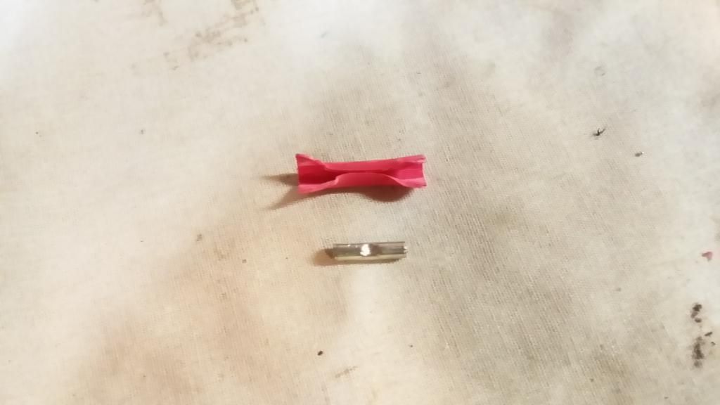
Butt splice insulation split...
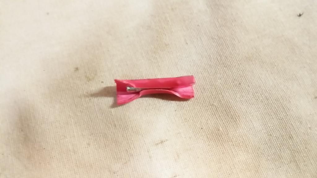
...and the metal splice removed from the plastic shell.
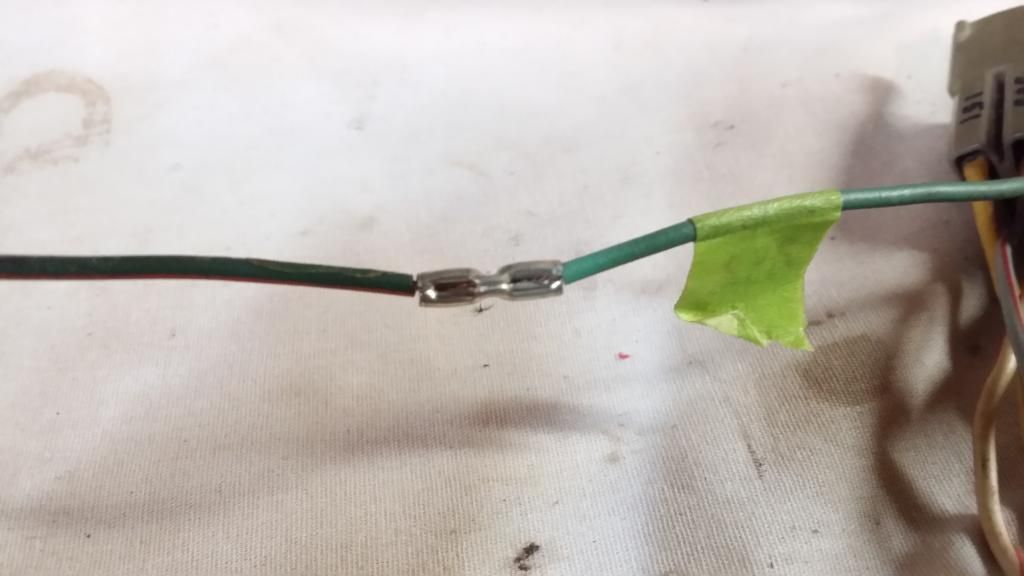
When I splice wires together, I make a mechanical crimp as well as solder the connection, after the mechanical crimp. My reasoning for this is if the wire gets hot enough, with just a soldered connection, the solder could melt out of the splice and let the 'hot' wire come loose, ground out and start a fire. With my approach, if the solder melts out, the mechanical crimp will keep the wire captured inside the splice.
I slide a piece of heat shrink on the side that has the longest wire length to get the heat shrink as far away from the soldering iron as possible.
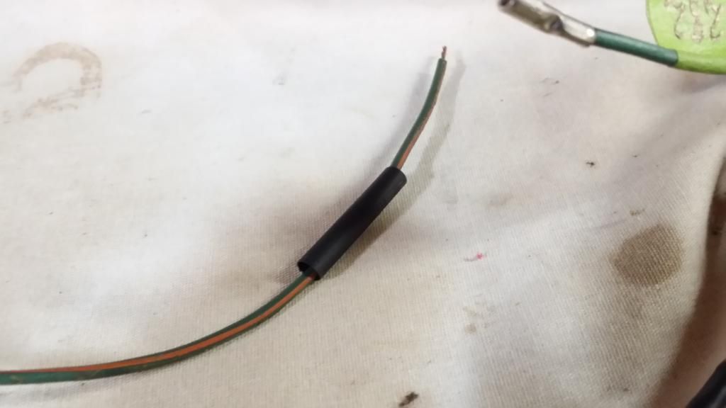
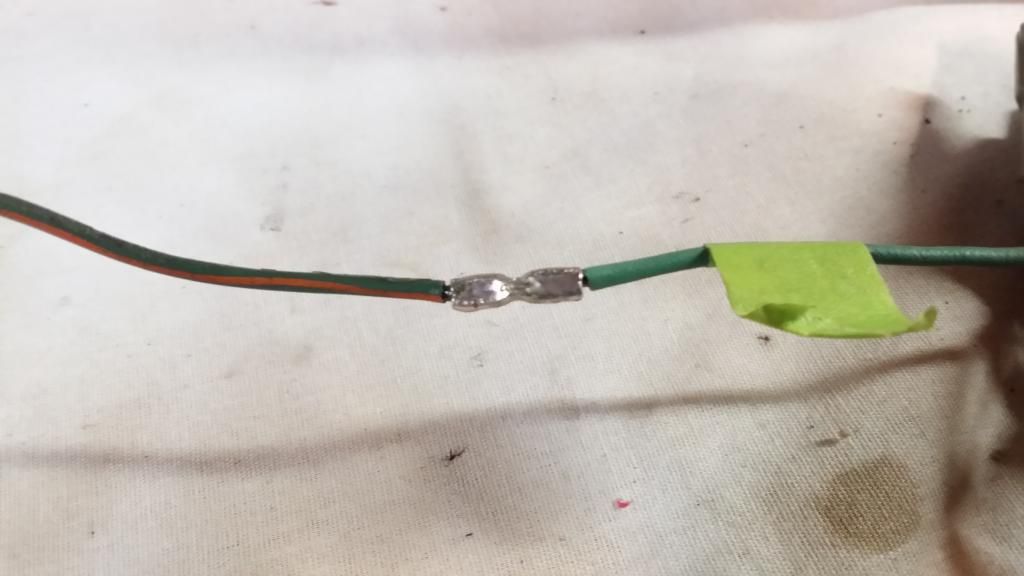
After I mechanically crimp the wires in the butt splice...
...I back-fill the butt connector with solder. This not only gives strength to the joint but, gives 100% continuity of the wires through the butt splice.
After that, I slide the heat shrink over the butt splice and apply heat to shrink it over the connection.
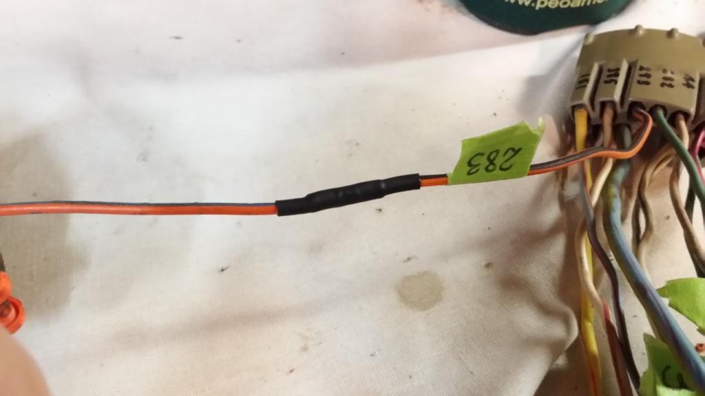
I also try to stagger the splices so they aren't all in the same plane, side by side.
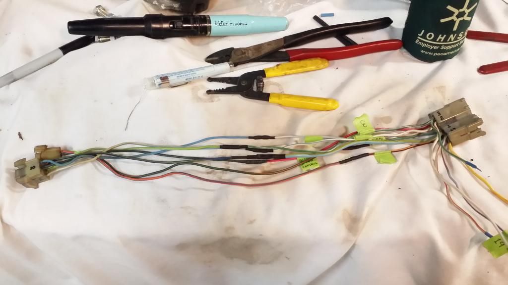
Patch cable installed BETWEEN the column connector and the original connectors of my '69 's main dash harness --no original main wiring harness wires were butchered during this production!
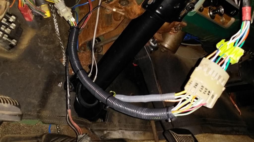
I still have to tuck and secure the patch cable under the dash but, I was testing out the circuits to make sure they worked. --the wires in the small gray split loom contain some wires that I've got to run to the emergency flasher switch in the glove box. They'll be wired in parallel so either the switch in the glove box or, the switch on the column will turn the hazard lights on.
The larger yellow wire in that bundle is for future use ...it will eventually be the signal wire to the cruise control module, when all of that gets installed.
Over the past week, I've been looking at wiring schematics for a '69 F100 and a '78/'79 F150, in order to decipher what wire ties to what, from the new wires of the '78 column to the old wires on the main under dash harness of the '69.
The wire color codes of the '69 wasn't a problem to sort out but, none of the wiring color codes for the '78/'79 were a 100% match between the new tilt column turn signal switch and the donor main wiring harness connector/pigtail I got from a '79 truck (without tilt/cruise). --this is what took some time to figure out, by reason of deduction, in spite of some wiring color codes being way off from the schematics.
The connector of the tilt column had a large, single, gray connector that all the column turn signal wires were contained in. The '69 column harness had two separate connectors at the ends that tied into two connectors under the dash.
Gray connector/pigtail from main dash wiring harness side of the '79 donor truck.

I didn't want to cut and butt splice (butcher) ANY of the original dash wiring harness of my '69 so, after looking at the situation, the apparent solution was to make a short patch cable to go in between the single column connector and the two original connectors under the dash.
Since I no longer needed the old turn signal switch from the '69 fixed column, the logical solution was to cut the wires on it, to be able to reuse the original pair of connectors and splice them into the '79 main wiring harness pigtail/connector from the donor truck. This would allow me to 'patch' in between the column connector and the original '69 Main dash wiring harness connectors, without chopping up the original main harness.
On the left, my turn signal wires/connectors I clipped off my old '69 turn signal switch. '79 connector/pigtail on the right, I cut from the main wiring harness of the wrecking yard '79 donor truck.

I laid the two sets of connectors out (cut wire end to cut wire end) and began splicing the wires together. When I butt splice wires, for use on a vehicle, I cut the plastic covering off. The plastic insulative covering just adds bulk and if you have multiple wires to connect, a lot of butt splices with the plastic insulation on them will just be a big knot in the bundle of wires, where the splices are. (doesn't look very professional).
Butt splice insulation split...

...and the metal splice removed from the plastic shell.

When I splice wires together, I make a mechanical crimp as well as solder the connection, after the mechanical crimp. My reasoning for this is if the wire gets hot enough, with just a soldered connection, the solder could melt out of the splice and let the 'hot' wire come loose, ground out and start a fire. With my approach, if the solder melts out, the mechanical crimp will keep the wire captured inside the splice.
I slide a piece of heat shrink on the side that has the longest wire length to get the heat shrink as far away from the soldering iron as possible.

After I mechanically crimp the wires in the butt splice...

...I back-fill the butt connector with solder. This not only gives strength to the joint but, gives 100% continuity of the wires through the butt splice.

After that, I slide the heat shrink over the butt splice and apply heat to shrink it over the connection.

I also try to stagger the splices so they aren't all in the same plane, side by side.

Patch cable installed BETWEEN the column connector and the original connectors of my '69 's main dash harness --no original main wiring harness wires were butchered during this production!

I still have to tuck and secure the patch cable under the dash but, I was testing out the circuits to make sure they worked. --the wires in the small gray split loom contain some wires that I've got to run to the emergency flasher switch in the glove box. They'll be wired in parallel so either the switch in the glove box or, the switch on the column will turn the hazard lights on.
The larger yellow wire in that bundle is for future use ...it will eventually be the signal wire to the cruise control module, when all of that gets installed.
#135
12-22-2014, 12:12 PM
Cargo Master
Join Date: Nov 2005
Location: La Ribera, Baja, Mexico
Posts: 2,694
Likes: 0
Received 43 Likes
on
25 Posts
Thanks a million Ultra, (Mil Gracias), I am saving this forum to my Truck's file, so when I find a 78/79 tilt column, and swap it into my 67/72 F250, I will have your 'Trailbreaking' to follow. I already have mixed & matched, the 67 cab, onto my 72 chassis, and had to blend the 67 wiring to the 72 steering column. Ford had changed a bunch of wiring so it was a puzzle to solve the lights, turn signal, and column wiring in the swap.
To help in identifying which wire was which, I purchased a TONE GENERATOR AND AMPLIFIER PROBE. IT IS MADE BY STEREN. I have used it to identify wiring very successfully. On the tool, it is called a 'Cable Tracker, HER-253.. There is a sender, and a receiver. Sounds like you already solved which wire is which, but in the future, one of these tools should help any of us following your lead...
Baja