When you click on links to various merchants on this site and make a purchase, this can result in this site earning a commission. Affiliate programs and affiliations include, but are not limited to, the eBay Partner Network.
Since he relief cuts were welded closed from both sides of the frame, I figured there would be sufficient strength to grind the outside welds avoiding the repair being Frankenstein-level obvious. Here are a few pics to illustrate.
The top rail of the passenger side frame horn.
The bottom rail f the passenger side frame horn.
This area will get additional strength from boxing the frame. Boxing will be tricky because of the irregular contours and, especially on the driver side where routing and mounting the power steering cooling lines will need to be worked around. Given that obstacle, it might be wise to look into alternate ways of cooling the power steering fluid. Ideas?
Next up will be the final shaping of the end of the passenger side frame horn, including bumper mounting holes. This should be a fairly straightforward operation.
Before boxing the frame, though, I want to fabricate and install a 2" square tube crossmember somewhere between the radiator crossmember mounting holes and the bumper mounting holes. The design goal here will be to avoid making these two important mount points harder to access as well as keeping it out of sight behind the grille shell. That may require temporarily mocking up the radiator crossmember and grille shell.
Thing three times, measure four times and weld once.
Updates are en route. The next piece will be on measurements that need to be done before making the frame so stout that it cannot be adjusted. That involved a rather unfruitful exploration of the CD version of the 1976 Truck Shop Manual. So stay tuned.
The following chronicles an unexpectedly difficult quest for authoritative information (numbers) to use in guiding this repair.
Although I did find high resolution chassis drawings at FORDification.net, those �body builder� drawings did not include the key dimensions that would tell me that my frame horn straightening was close enough to stock to look right and be functional when radiator crossmember, radiator, grille shell, fenders and bumper were replaced. Here is the relevant portion of those chassis diagrams:
By the way, these are called �Body Builders Layout Books� because, I suppose, the intended audience was the builder of custom bodies for Ford frames and power trains. Here is a more contemporary collection of body builder info from Ford. Body builders really only need information that will enable them to build bodies or body components that will fit what comes to them from the Ford factory. Unless there is more to these body layout books than is currently available online, they are not going to provide what I need.
Somewhere there must be references for body/frame repair services that provide key dimensions that would guide the repair process but I was unable to locate them. Since the copyrights should have expired, scanning and posting such information would be a great contribution. The Bronco Graveyard has already done this for Broncos.
There is a commercially available CD with scans of the 1976 Truck Shop Manual (Amazon $22.68) which I purchased in the hope that it might contain the information I would need to determine whether the repaired frame horns were within factory specifications.
Unfortunately, I did not find the information I was seeking. This manual does treat the topic but offers only general guidelines as follows.
Frame Inspection (page 2188)
Frame misalignment can effect front end alignment and cause improper operation and / or abnormal wear of chassis parts.
Before checking frame alignment, inspect the frame for damage and loose parts. Inspect all frame members for cracks, twists or bends. Check all welded connections for cracks. Inspect all rivets, bolts and body support brackets for looseness. Make all necessary repairs or replacements. Diagonal or X Frame Checking Method
Frame alignment can be checked without removing the truck body from the frame by using the diagonal or X checking method.
Place the truck on a clean, level floor and set the parking brake.
Select several points along one frame side member and very carefully transfer these points with a plumb bob to the floor. If desired, paper can be taped on the floor along both sides of the truck below the frame. Mark the points on the floor as accurately as possible.
Locate the corresponding points along the opposite frame side member and very carefully transfer these points to the floor in the same manner.
Move the truck away from the marks on the floor and measure between diagonal points. Both corresponding measurements should be equal 1/4 inch. Measure diagonally between all points on the floor.
Measure between corresponding points parallel to the frame side members. These measurements should be within 1/4 inch of each other.
The squareness of the frame side member web and the lower flanges at the spring hangers should be within 1/16 inch. The squareness of the side member web at the steering gear mounting location should be within 1/16 inch. The web and flange should be square at all other locations within 1/8 inch.
Any point on one side member should be within 1/8 inch ahead, behind, above or below the corresponding point on the opposite side member. The frame side member should not vary more than 1/8 inch.
Frame Straightening (page 2189)
Frame misalignment can be corrected by straightening the out-of-line parts or by replacing the crossmember, braces or brackets if they are badly damaged.
To prevent internal stresses in the metal, frame straightening should be limited to parts which are not severely bent. If heat is needed to straighten a frame member, keep the temperature below 1200 degrees F (a dull red glow). Excessive heat may weaken the metal in the frame members and cause permanent damage. Do not apply heat to 50,000, 80,000 or 110,000 PSI frames
Frame Reinforcing
After a bent frame member has been straightened, inspect the member closely for cracks. If any cracks show, the frame member should be reinforced or replaced. If the frame is a 50,000, 80,000 or 100,000 PSI frame, no repair method is approved.
Reinforcements can be made from channel, angle or flat stock. The reinforcement stock should be of the same material and the same thickness as the frame member being reinforced and should extend a minimum of six inches to either side of the crack.
To ensure sound repair, the crack should be prepared before the reinforcement is welded to a cracked frame member. Do not weld 50,000, 80,000 and 110,000 PSI frames. The only frame that welding is permissible on is the 36,000 PSI frame. The cracked area should be wire brushed to remove paint and expose the crack. To prevent the crack from spreading, drill a 1/4 inch hole at the root of the crack. Grind out the crack to form a slot which will allow the weld to penetrate to the surface of the reinforcement.
The proper location of the reinforcement depends upon the location of the crack. If the crack is at the bottom of the channel, an additional reinforcement should be welded to the side. Drill clearance holes in the reinforcement to clear rivet and bolt heads when necessary.
Frame Member Replacement
If a damaged frame member is to be replaced, new bolts, grade 8 fasteners and rivets required for replacement of parts, should be of the same specification as the original bolts or rivets. It cases where it is necessary to substitute a bolt for a rivet, use the next larger size bolt.
There�s lots of other useful info so I�m sure that I will eventually get my money�s worth from this CD. I should mention that it contains one PDF (5 volumes, 2443 pages) that is heavily encumbered with DRM (digital rights management). One is prevented from making screen shots, copying text to the clipboard and printing more than a page at a time. The quote above had to be transcribed one letter at a time.
Having gone down all of these dead end roads, I realized that my having an undamaged reference vehicle would be essential. The fact that my F-100 was partially disassembled meant that I could conveniently take measurements from it. That was a huge bonus.
So, having an undamaged F-100 as a reference to take measurements from was essential for me. I should note that the inclusion of the F-250 in the body builder diagram above is a bit misleading because that frame is not interchangeable with the F-100 and F-150. The F-250 frame is made of a much thicker steel and has larger vertical dimensions. Initially, I had thought that since the body pieces are interchangeable, the same would be true of the frames. Had they been interchangeable, the frame horns from my �77 F-250 parts truck would have simplified maters considerably. Fortunately, almost everything else on the parts truck will be usable.
Satisfied that I had the best specifications available, I set out to see how close my F-150 frame straightening results were to the dimensions of the undamaged F-100. The next episode will show those numbers and foretell what comes next.
The most critical measures are those that locate the radiator crossmember because that member is what aligns the whole front clip. If it is off in any significant way, nothing else will fit correctly. Dimensions that locate the bumper are secondary to that.
The first step was to determine if these mounting points are the correct distance forward of the undamaged engine crossmember. The motor mount bolts go through the top rail of the frame and the engine crossmember so are excellent locator points. There are three motor mount bolt holes on either side of the frame but only two per side are used. This is to allow the motor mounts, which are shaped differently from one another, to be swapped side-to-side for vehicles sold in countries like Australia where right-hand drive is required.
Here is the passenger side motor mount where it attaches to the top rail of the frame:
Note that the arrow points to a bolt hole location that is normally left unfilled on left-hand drive (e.g. U.S.) systems. I added a bolt here so that the hoped-for measurement would be the same for both passenger and driver side. While I was at it, I tightened all of the motor mount bolts on both sides.
Here is a view of the driver side where one can see how this motor mount uses the frontmost bolt hole. On this side, the rearmost hole is unused but not visible because the steering gear obscures it.
Doing a little wire brush clean-up on the driver side motor mount revealed a crease in that motor mount that caused some concern that this might be damage that escaped notice earlier.
However, I checked the driver side motor mount on the reference F-100 and, to my great relief, found the same kid of crease there.
On the undamaged reference vehicle, the distance between the frontmost motor mount hole and the center of the radiator crossmember on the driver side is 21 inches. The driver side of the repaired frame has the same measurement as shown here.
The same result was achieved on the passenger side.
As well, the distance from this bolt to the topmost bumper bolt hole was also correct.
Turning next to the distance between passenger side and driver side mounting points, it turns out that 32" is a bit of a magic number.
As you can see, everything is 32" apart. Even the lower bumper bolt holes are 32" apart.
The height of the frame rails from the floor is the same side-to-side and, so, also level according to my 48" carpenter's level.
But is the frame square in this repair area? Earlier diagonal measures determined that the frame from the engine crossmember back toward the rear axle was square. So, it is time to use that same technique on the repaired area.
There is a rivet on the lower frame rail that goes through the engine crossmember followed by the lower frame rail and the spring tower. Using this as a reference point allows an uncomplicated straight line measure directly to the radiator crossmember mounting hole on the opposite side. This yields a diagonal or X measure which should be the same on both sides.
The reference vehicle was square measuring 36.5" in both directions. The same measurements on the repaired area yields slightly different numbers for each side. It is not square.
Moving both frame rails 0.5" or less toward the passenger side should correct the situation. This would be relatively easy to adjust if we were working with commercial frame straightening equipment. Coming up with a shade tree equivalent will be an interesting challenge.
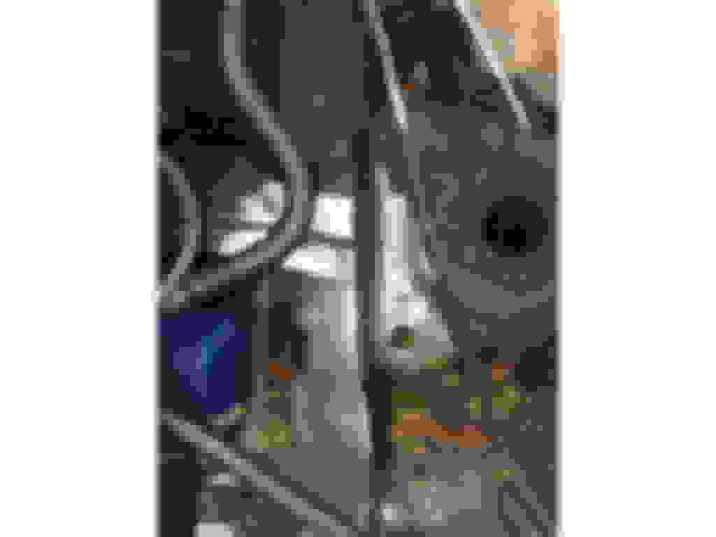
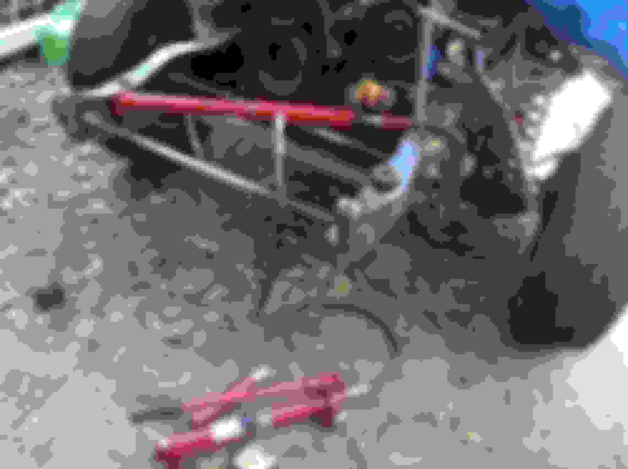
To make that last little adjustment to the frame, I pulled out the 10 ton hydraulic ram placing a wedge right where the driver side frame needed to bend like this:
I placed the other end on the heavy 1.5" thick form currently attached to the front of the passenger side frame horn as pictured here:
A little heat applied to the both sides of the frame where it meets the engine crossmember and a little force from the hydraulic ram squared-up the front frame horns. The home made fixtures that tie the frame together side-to-side played an important role in making sure that the force was evenly distributed to both sides of the frame.
Now, the measure from the engine crossmember rivet to the center of the radiator crossmember hole is 36.5" on both sides and the same as on the frame of the undamaged reference vehicle. Checking all of the other dimensions confirmed that none had been changed in the process. The last check will be to mock up the radiator crossmember and the inner/outer fenders. After that, making the frame more rigid with frame boxing and a crossmember will follow.
While the ram was out, I placed it behind the form on the passenger side like this in order to prevent hammer blows from affecting or being absorbed by the rest of the frame.
I then used a cutoff saw to make three incisions, added some heat and hammered away with a 2.5 lb hammer and a slapping spoon. Results look like this:
As was done on the drivers side, these cuts will be welded up on both sides.
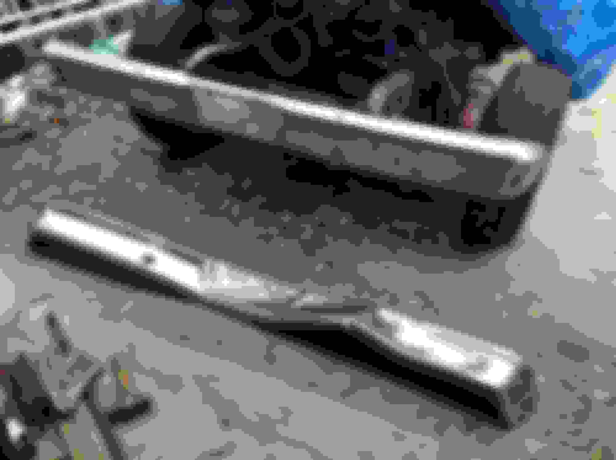
Having adjusted the shape of the frontmost part of the passenger side frame horn by making a few relief cuts, heating and hammering over a solid steel form, it's time to weld up those relief cuts like so:
... and so:
The welding (oxyacetylene) is done on both sides. Although I really don't like welding against gravity (on a creeper), I don't think its possible to overstate the importance of doing so. As you do it, it becomes clear that bonding to both sides of a cut like this and getting sufficient penetration simply cannot be done from one side alone. This becomes especially important if the weld is subsequently ground down for fitment or aesthetic reasons.
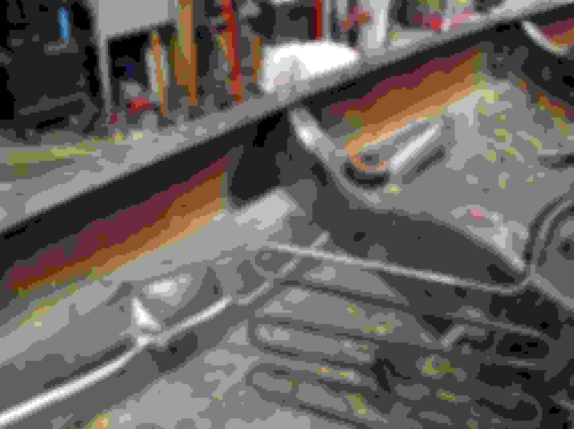
Here, the result of grinding with a 36 grit 7" disk can be seen.
The ultimate test of restoring something to original specs is whether the stock parts bolt on and fit as they were designed to do. Here, we see the original, crushed bumper on the ground (note signs that it was removed by grinding off the heads of the bumper bolts) and the replacement bumper bolted up to the repaired frame horns.
Those bolts are common carriage bolts gotten from Ace Hardware and a bit longer than stock. The replacement bumper is from a 1977 F-250 Camper Special so there's a lot of interchangeability in these 6th generation Ford trucks (dents) and possibly beyond that. This isn't a perfect bumper but it will do for now. Here are a few pics showing the connection to the frame. It bolted right up without any need for coercion.
The most critical fitment check is the radiator x-member because so much is aligned to it. The inner fender wells, the outer fenders and the hood - all of that has to fit together and look halfway decent.
The holes where the radiator x-member attaches to the frame appear to be in the right place. For the trial fitting, I'll use the bolts and runner biscuits from the F-100 reference vehicle. For final assembly later on, I'll use new units from Dennis Carpenter Reproductions.
I have three radiator x-members as seen in the following pictures. First up is the x-member from the 1976 F-100 reference vehicle. It is straight but rusty.
Next up is the x-member that was on the 1976 F-150 truck when the collision occurred. It has some rather significant damage as you might imagine.
Finally, I have the x-member from my parts truck, a 1977 F-250. It, too, has a bit of damage from some previous encounter.
Looking at the original x-member reveals quite a bit of damage. In the next picture, one can see where the inner fender made an impression and where the crossmember was bent along a line running through that part of the frame where the x-member is attached.
The frame was so damaged that the x-member attachment bolt was ripped through the x-member.
In addition to that, there is a tear and some warpage toward the center on the frame side of the x-member.
Looking at the 1977 F-250 x-member, one sees several tears in the sheet metal on the passenger side. Here are three that were probably caused by a previous fender bender.
A close-up of two tears.
Finally, a stress crack or tear in the frame side of the x-member about halfway to the center from the passenger side.
All of these x-members are the same with the exception of an additional bracket for a heavy duty radiator on the F-150 and F-250. The F-100 uses a radiator with fewer cores and the fan doesn't have a clutch as the other two do. Instead, the F-100 uses a plastic cowl around the radiator. Other than that exception, the x-members are identical and interchangable.
So which one to use?
Clearly, the original 1976 F-150 x-member is not a good candidate. It may be partially or fully recoverable later on but prudence dictates that it be set aside for the time being. It won't make a good measuring stick.
The 1976 F-100 x-member would do the job but can't be retained by the F-150. The undamaged F-100 is next in line for refurbishing and will need that x-member. Nonetheless, it can be a good point of reference.
That leaves the F-250 x-member. Getting that piece up to standard will not only provide a good measuring stick but will also serve as the x-member that the F-150 lives with from now on.
So the thinking is that repairing the slightly damaged F-250 x-member is the best way to test for fit and provide an x-member for final assembly. Of course, the F-100 x-member is there should it be needed as a double-check.
I just wanted to say that I really appreciate every comment that has been offered here. They've been encouraging and informative and, best of all, civil. I call out civil because that is becoming a rare thing in on-line communities these days. I've abandoned several in the last few years for this very reason. We can argue the merits of this or that without casting aspersions on the persons holding those opinions.
So, thanks so much and please do keep those comments coming. I've had many a doubt as this project has unfolded but your support and encouragement have always pulled me through.
Flowney, Starting an undertaking like this one with no experience in frame straightening is a testimony to what a person can do with just GOOD common sense and a desire to try something different; ....just for the sake of saying you did it. It is a good feeling when a person has a proper outcome! If you had to do another damaged frame (yeah,I know ,you'd shoot yourself first!) ,you would cut your labor time in half;the next one even more, as a person goes directly to the step 1,2 or 3 from experience now logged in your frame straightening brain.. This has been a great tutortorial (sp?) for folks tackling ANYTHING that seems exotic or beyond their capabilities.Great pics,text and above all great job! GARY


 10-31-2014, 12:49 PM