When you click on links to various merchants on this site and make a purchase, this can result in this site earning a commission. Affiliate programs and affiliations include, but are not limited to, the eBay Partner Network.
Hello again all. Thanks to you guys Old George has been toolin down the road this summer up here in the Far North.
It's time however for some new brakes. I'm in the process of installing the CPP disc conversion up front along with the CPP power booster, the rear will be drum brakes on a 9". I've read a lot and want to confirm a couple of things and ask a few questions. Dad wants to help work on the truck when he gets here next week to visit and I'd like to have everything ready. My questions at this point are concerning hooking up the booster break lines.
Confirm:
- I understand I will need a 10# residual for the rear drum brakes and a 2# for the front disc?
- This is the proportioning valve?
Questions:
- If this is the proportioning valve, and I get the residual valves, and figure out what connection I need to hook up my brake lights, will this be everything I need?
- Where do I hook up the vacuum line? The instructions mention it but there is no schematic or diagram of what is what and what goes where.
- Does the vacuum line come off my carb?
- Where do I hook up the rear lines to and where do I hook up the front line?
I believe this metal plug is covering one of the ports that I will have to connect my lines to.
Here is the other side (notice no plug).
Not sure why one side is plugged and the other isn't (maybe for bench bleeding purposes??)
- What's the white plastic piece in the first picture?
- What's this thing covered by a black cover?
Pictures would be great if you have any of your install. Thanks in advance for your help!
So far so good.
here is from CPP: Classic Performance - Proportioning Valve Kit Installation
Note that the switch in the proportioning valve IS NOT a brake light switch, but a "system failure warning" switch. You will need to add a brake failure warning light in the cab if you wish to use this feature. A separate brake light switch will need to be installed, or there may be one (or a port for one) on the MC. If not, a mechanical switch can be installed to activate against the pedal arm.
The black "cap" is actually the front brake delay metering valve adjuster.
You can "home run" separate lines to each front wheel, but it is more common (and easier when installing the residual valve) to run one line to a T fitting at the front crossmember then branch to each wheel. The residual valves are installed somewhere in the front and rear main lines before they T, be sure to mind the flow direction. When installing the flex hoses be sure to check for clearances rubbing when the front wheels are fully turned in both directions, you may need to substitute different length hoses. When running your hard lines, use lengths of 1/16 TIG welding rod (available from welding suppliers or at your local DIY store in the tool dept.) to plan the routing/bends. Use a tubing bending tool to make your bends. Be careful not to kink or pinch the tubing when bending or installing. If you kink or miss-bend a length DON'T try to restraighten, rebend or fix it, throw it away, it's cheap. When routing, make sure the tube does not rub against anything, especially if going thru a hole such as in a crossmember, it should not touch metal edges (hole should be way oversized if making a new one) you can make a grommet for any size or shape hole for extra protection: cut a slit in one side of a length of rubber windshield washer hose, slip over edge of hole, trim to length and glue in place with a dab of weather stripping glue). Support the tubing with matching sized neoprene cushioned hangers (available at auto parts stores or in the low voltage electrical area of that DIY store. Self drilling metal screws and a socket adapter in a VS drill or powered screwdriver will make installing the clips a breeze. Install a clip close to each side of a fitting or pass thru, and every 16" or less on long runs. Mark of a good installation is the tubes are straight between smooth clean bends, run neatly. NEVER run brake lines on/across the bottom of the frame.
When tightening fittings be sure to use fitting wrenches only (look like heavy box wrench with one hex side cut open. Be sure to check and match the fitting sizes, they may be fractional or metric sizes (typically 3/8 or 10 mm on brake lines, but don't mix fitting and wrench sizes, they are close but wrong one will round the fitting. The wrenches are double sizes ends, not real expensive, available at most chain auto parts, DIY stores and Sears (don't buy at Harbor Fright or off a bargain table!) so buy/use the right ones. NEVER use a pair of pliers, open end, or adjustable wrench on a brass fitting! Use two wrenches when screwing fittings together!
The vacuum hose (be sure to use vacuum tubing) should be run from the booster to a source of engine (rather than carb base) vacuum. Typically there is a port near the rear of the intake manifold. If you didn't have power brakes attached to the engine before you may need to remove a plug and install the correct NP to hose barb fitting. You can verify that it is a vacuum post by removing the plug with the engine running and put a finger over the hole. You should feel a significant suction, and the engine will likely run rough and stumble with the port open. Be sure the hose cannot contact any hot exhaust parts or linkages.
Follow AX's directions and you will do fine. A couple of things I found when I did mine (I replaced everything, used Speedway's disc kit, and had to make my own mounts for a PB system for a mid fifties car). Flaring brake lines sucks - period. I could not get the flares to come out straight. I tried three different flaring tools (the cheap type of course). I ended up at NAPA after measuring what I needed. I was able to get pre made lines with the fittings and flares already done (generally $4-7 each with fittings) and then just had to bend them to fit.
I just ended up getting my residual pressure valves off of the net (10 lb for the rear and 2 lb for the front).
Not sure if the CPP kit came with it, but I also replaced the soft line that goes from the rear axle to the frame. It is the "Y" fitting that splits the single rear brake supply line to each side of the rear axle:
Great FAST advice guys, thanks! I'll be printing it off and taking it tothe parts store.
To help clarify for folks in the future; I called CPP about the residual valve situation (since their schematic says it has a 10# on it). They said it only needs the residual valves if you mount the MC below the calipers. The kit that I bought is an under cab mount, so I wish they would have mentioned that when I purchased, but maybe I just missed that part........ In any case, just like has been mentioned before, you put a 10# on the rear before the T and a 2# on the front before they T. I will likely use the one that is plugged off to mount my brake light switch. I'd like to look into the pressure switch that mounts under the brake pedal though as I know it will light up sooner than the original style. Anyone want to share what you used for this?
The schematics from CPP you guys put up was a big help! Why I couldn't find them is beyond me........ but you guys come through again.
I'll keep this thread alive with updates a photos as best I can so we'll have a fresh source.
I hope my NAPA has everything I need, especially that rear house with the breather dmack. If not I'll have to order one.
My king pin bushing are getting pressed as we speak and I can start reassembly of the front next week w/ photos of course.
Here's what old George is looking like at the moment. I've been sanding off the old primer that was covering the even older patina. I also picked up a F2 for parts (seat/doors/hood/flathead 8). I love these old trucks!
I like the original green/primer/rust better than grey primer any day!
Hood from the F2
F2 parts truck after I grabber the engine/trans/radiator/seat/hood/doors/heater/glass. Sold it for 50 bucks less then I paid!
I just googled "brake proportioning valve install" and clicked on the images tab.
I don't know if a pressure switch will mount in a line port. Is there not a plug in the MC for one (typically at the end of the MC directly in line with the pushrod/piston) The 93 Camaro pedal set I used came with several switches mounted to the bracket for brakes, clutch and brake starting safety switches. These switches have plastic housings and are adjustable for activation point I wouldn't expect them to be terribly expensive from a discount parts dealer like rock auto
Here is a pic early in the pedal install. Note the 3 tabs with holes for the switches over the pedal arms. They are threaded with plastic nuts for adjustment. A simple bracket could be fabricated, the DD shaped hole that prevents the switch from rotating would take a bit of hand filing to shape.
Keep at it and enjoy driving it in between upgrades. Wish I could have, but the PO had the body blown apart and all of the components were a complete unknown. Two years later I am driving it every chance I can. I don't believe in fair weather cruising- I just like driving it.
Thanks Dave and AXracer! I'll see what I can come up with on the brake lights. I don't see anywhere I can hook up the original style other than on one of the ports for the front. CPP said that would be fine to use one of those so I guess that's what I'll go with for now until I find a switch I like. I have a couple more questions though.....
What size line did you use for the rear?
The port off the proportioning valve for the rear is way bigger than the front. It looks like 5/8 but must be metric because my 5/8 line I have doesn't fit. I'm just wondering how easy the juntion will be inthe rear if I have such a large line connecting the the flexible hose. Right now the truck has 3/16 all the way around.
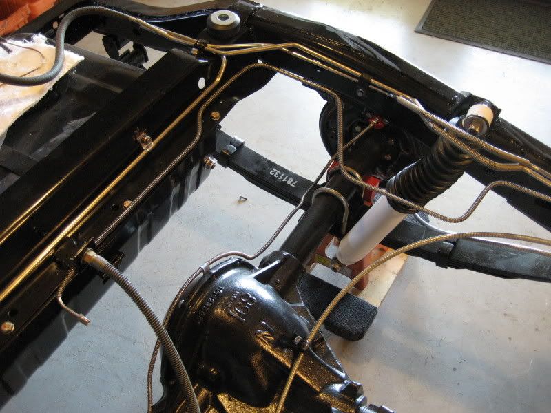
I take it that this is where you connect the vacuum line? The black piece with the yellow warning label around it.
And lastly, how does this thing come off? I just don't want to do anything stupid, but I tried to twist it off just like a bolt. Could just be rusted, but thought I'd ask before I really start messing with it.
If you have any issues getting a solid brake pedal you might want to get one of these little gems. It centers the porportioning valve and locks it in place, after bleeding remove the pin and replace the switch. I don't think that CPP includes it in their kit but other manufactures do. https://www.performanceonline.com/Co...ve-Bleed-Tool/
Thanks ChuckRob! I've never heard of those before,but I've already got it on order. I've never bled brakes on a vehicle before so if anyone has any other tips I'd love to hear them. Thanks,
For the rear line, I used the same 3/16" line as the front. NAPA had the different fittings on the same line available, just take your valve block and match up the size fitting you need.
For the rear line block on the axle, yes, just turn it out like a bolt. The vent tube on mine was plugged, so I ran a drill bit through that fitting center (the hose nipple sticking straight up). Then just ran a piece of fuel line from it up to the frame for the vent.
On the booster, yes, just hook manifold vacuum up to that fitting.
I'd recommend cutting a new inspection port in the floor over the repositioned MC fill cap. Filling the MC and bleeding will be a real chore, trying to get fluid into the MC and seeing how much is in it will be a real exercise in frustration!
I'd recommend cutting a new inspection port in the floor over the repositioned MC fill cap. Filling the MC and bleeding will be a real chore, trying to get fluid into the MC and seeing how much is in it will be a real exercise in frustration!
Hey Ax Is there any particular starting point when it comes to running brake lines? Can You start at the rear and work your way to the master cylinder? Or master cylinder to front then master cylinder to rear.Thanks Brian. Didn't mean to hijack sere0501 thought this would be the appropriate place to ask sense it was related to brakes.
Thanks Dave and AXracer! I'll see what I can come up with on the brake lights. I don't see anywhere I can hook up the original style other than on one of the ports for the front. CPP said that would be fine to use one of those so I guess that's what I'll go with for now until I find a switch I like. ...
I don't see how that can work. Ports on a MC or proportioning valve are straight threads for flare nuts; hydraulic brake light switches are tapered pipe thread.
Hey Ax Is there any particular starting point when it comes to running brake lines? Can You start at the rear and work your way to the master cylinder? Or master cylinder to front then master cylinder to rear.Thanks Brian. Didn't mean to hijack sere0501 thought this would be the appropriate place to ask sense it was related to brakes.
My preference is to start with the longest lines that can be run in one piece between fixed points, such as from front T to pass side flex line, from rear T to rear axle wheel cylinders. I also like to use 1/16" TIG or uncoated brass or steel gas welding rod in 3' lengths to plan the routing/bends. Determine the bend radius your tubing bender makes and match it with a round object strong enough to bend the wire around. Keep the straight sections as straight as possible and directly to a supporting surface avoiding diagonal runs for a clean installation. Don't run a line tight between fixed points. Put in a small Z bend to allow the tube to shrink/expand with temperature changes. Avoid running lines higher than MC. Use a short premade line between proportioning valve and residual pressure valves. Preplan lengths so that you can use the R-valves as couplers between two tubes. DO NOT run brake lines on the bottom or across bottom of frame. Do not run lines in the air unsupported for more than 6 - 8".
And lastly, how does this thing come off? I just don't want to do anything stupid, but I tried to twist it off just like a bolt. Could just be rusted, but thought I'd ask before I really start messing with it.
Thanks fellas, and have a great weekend!
It just unscrews. put a box-end wrench or 6 point socket on the breather vale and unscrew.
As stated flaring brake lines can be a PITA. I managed to use pre-made lines for all but one of my lines. I took the lines off tried to straighten them out and measured them. On the line going to the rear I had to get a union and use two lines but that way I avoided the risk of leaks. Just an option.
I read here that some parts stores (I think they said NAPA) had the ability to flair brake lines if you need to go that route.
 07-10-2014, 10:34 AM